The Solder : Time II is the latest version of our Solder : Time watch kit. This new version is even more hackable than ever. The on board microcontroller in this model is the very popular ATmega328P used in many of the current versions of Arduino™. In fact, you can reprogram your watch using the same Arduino™ IDE software that you use for a regular Arduino.
The Solder : Time II is different from the original Solder Time in many ways. The display has been upgraded to a set of four 5x7 LED matrix modules. This gives you control of a 7x20 matrix for a total of 140 LEDs!
The new LED matrix allows for an amazing amount of information to be displayed; aside from the current time... The date, month, words, scrolling messages, graphics, special characters ... the possibilities are endless.
The ST2 comes with a piezo buzzer for the alarm function, but you can also use it to add sounds to you custom programming and games.

Tools and supplies required :
• Soldering iron
• Solder
• Flush cutters
• Masking tape


Solder the battery holder in place with the open edge facing down.
Taping the battery holder in place, with masking tape, when soldering works best.
Note: Some people like to solder a small blob of solder onto the center of the round battery pad for
better contact with the battery.


The crystal for the real time clock is the very small silver colored part with two leads.
Solder this as in the photo.

Note: The leads on the crystal are very small and seem to not heat up easily. So, when you solder the crystal in place be sure to have contact with both the pad on the PCB and the crystal’s leads with the soldering iron.

Place one of the 5x7 LED matrix modules onto the PCB. Push flat, making sure all the legs go through the holes.
NOTE: Make sure that the code numbers printed on the edge of each of the LED matrix are facing the left side OR the bottom of the watch (as viewed with the watch held like in the photo).
Solder two of the leads (opposite sides) and then work on the next LED matrix, repeat. When you have all the LED modules held in place go back and solder the remaining leads.

Trim the leads with a flush cutter.
Note: Go slowly with the flush cutter and do not pull up as you are snipping, this could damage the PCB traces. Also, be careful to not scratch the bottom of the PCB with your tool.


Prepare the buttons by cutting them from their packing tape, (rather than trying to pull them off).
Push each button into the PCB. It should almost click into place.
Solder and trim the leads.


Prepare the piezo buzzer by cutting it off of the packing tape, don’t try to pull it off the tape!. Next, cut off the two very small plastic protrusions on the bottom. See photo. These are cut so that the piezo will fit over the other parts in the watch.

Push the piezo through the holes. There is no polarity. Test the fit before soldering. It should sit relatively flat, if not check the plastic protrusions.
Solder and trim leads.


Slide the battery into the battery holder on the ST2 PCB with the CR2032 “+” label text facing up. When the battery goes into the holder the watch should turn on and display “Time” and then 12:00. If not, remove the battery and check your work. After about five seconds the display will turnoff, this is normal.
To run a “lamp test”, a test that lights all of the LEDs to verify that they are all lighting, press the left button while you slide in the battery.

If all is OK, each column, from left to right, should light one at a time, each starting at the top and filling to the bottom. If not check your battery and then your soldering job.
Peel the protective layer off of the plastic parts:
In order to protect the plastic parts during manufacturing they come covered by a thin plastic / tape layer. These should be removed before you assemble the watch. The color may be blue or white etc, but the watch body is always made of clear acrylic.
NOTE: Only use something soft like your finger nail to scrape the edge of the protective layer and then peel it off. Also only clean with a product like Windex, never use an alcohol based product, it will cause cracks in the plastic.

The bottom layer need to be prepared before the watch parts are stacked. Start by inserting the four (4) brass expanding inserts into the four round holes on the bottom.
NOTE: Make sure they are all pushed through from the same side. If you try to remove them you may crack the bottom layer.


Note: Be sure to support the area between the slots for the strap and the hole for the insert (center photo) with your finger while you press the brass insert into it’s hole.
With the fuzzy side facing the center of watch, feed the velcro strap through one of the wrist strap holes. Next, pull a length of velcro through the hole and feed it back down on the other side. Try it on your wrist. If it is comfortable continue, otherwise remove the strap and try the other holes.

With the battery in the battery holder start making a stack of parts.

NOTE: Some ST2 Kits may ship with one 3/16” Circuit Area layer rather than a 1/8” layer plus a second 1/16” layer.
1. Start with the prepared plastic watch bottom oriented with the programming port at the top.
2. Next, place the plastic PCB layer with the battery notch facing down.
3. Drop the PCB with battery installed in the round plastic PCB layer. Make sure the battery is lined up with the battery notch.
4. Place the first of the two circuit area plastic layers on top of the PCB layer plastic.
5. Place the second circuit area plastic layer on top of that.

NOTE: Cut-out for crystal leads goes on the left side
6. Place the front face of the Solder : Time II on the top of the stack.
7. Using your fingers, screw the layers together with the included screws. Don’t tighten them (this will help you align the layers).
Before tightening the screws check the watch;
1. Are the sides even?
2. Is the PCB getting pinched?
3. Do the two top buttons move freely and click when pressed?
4. Is the display flush with the top?
5. Is the notch for the battery lined-up with the battery.
If you answered “no” to any of these questions try this;
Uneven, pinched or not lined up: loosen screws and rotate body parts until they line up and or with screws in but loose roll watch on it’s side edge with your hand on a flat surface.
Budging, display sticking up or buttons getting stuck: remove PCB and check that the component leads are trimmed flush with PCB. Look for any other out of place parts.
Once you are satisfied with the fit you may tighten the screws. But do so gently, the watch is made out of plastic. If you try to over-tighten the screws you will crack the acrylic housing. Also, once the screws are tightened, recheck that alignment and that the buttons move freely.


The user input interface for the ST2 is made up of two buttons. We call the left button the “SET” button, and the right side button “MODE”. There are three distinct input states, pressing one of either of the two button or pressing both at the same time. The current version of the ST2 firmware does not use a timed button press, meaning it looks for a button press and no current features use a “press” longer for some other function.
Below is a flow chart of the program flow in the ST2. Basically you press the MODE button to jump to the next function. Then you press a combination of the SET or BOTH buttons to have the correct interaction.
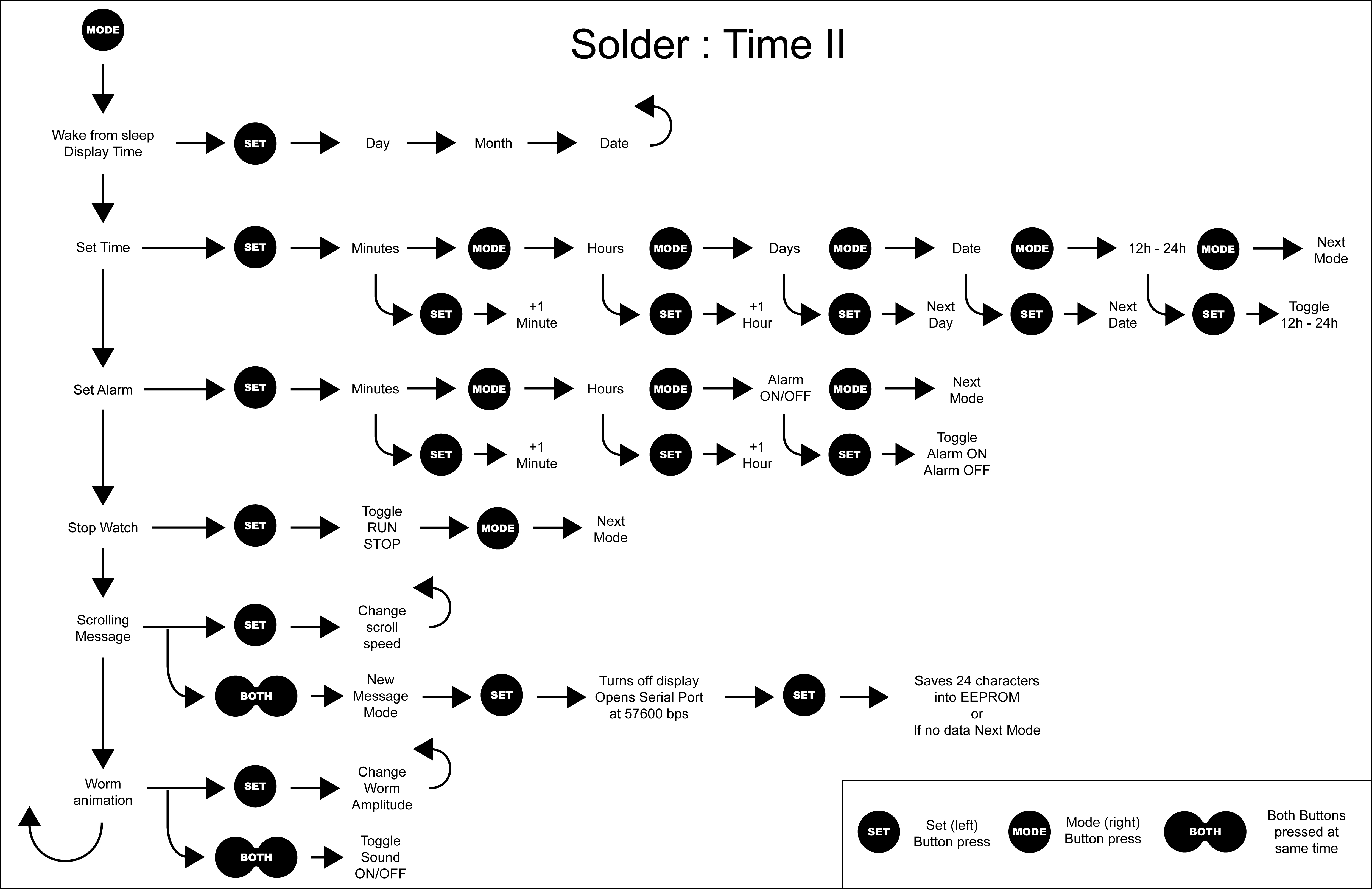
Click to open larger size.
The ST2 is based on the ATmega328P. The ATmega328P is a general purpose micro-controller, which is also used on many of the Arduino models including the UNO. Because of this, you can use the Arduino IDE to reprogram the ST2.
The ST2 spends most of it’s time in low power sleep mode. In this mode, the RTC (real time clock) is still keeping time, however the entire ST2 is in low power mode.
The ST2 wakes from sleep by one of two events. The MODE button (right) is pressed or the interrupt line from the RTC to the ATmega is asserted low. The interrupt goes low when the alarm is triggered in the RTC.
Once the ST2 is wakes up, the ATmega checks the current time by communicating with the RTC chip over a two wire bus called I2C. After waking, the ATmega checks why it woke up, Alarm or button press. If the alarm has tripped, the buzzer is buzzed and a message displayed. If a button was pressed, the current time is displayed.
When the watch is not in low power sleep mode, its program is constantly running in a loop. In order to have different distinct operating modes the program loop runs a state machine using the “switch” statement. This way we are able to have the watch act like it has a bunch of different programs running on it.

In order to switch between the different modes of operation, the two button interface is used. In general, when the Mode (right) button is pressed a flag is set “NextStateRequest”, and when the Set (left) button is pressed the “NextSUBStateRequest“ flag is set. The button presses (and alarm trigger) are checked in the main loop, but the flags are then handled in the sub-routines called by the state machine, this reduces repeating code.
There are two easy ways to add your own programming to the ST2. One is to replace one of the current states with your own code, the other is to simply add another state. You will also have to update the variable called “MAXSTATE” to the maximum number of states you are using. This way, you could use the Mode button to jump through the different states until you get the your new or customized state.
As we said above, the main program is running in a loop jumping through the different states. There is no state to actually draw (turn on or off) the LEDs on the LED matrix.
The ST2 uses something called an interrupt . This interrupt uses one of the built in timers in the ATmega, and a library called TimerOne.

How the timer interrupt works is a little like a timer on your oven. The program sets the number of microseconds for the timer to run until it “rings”. It doesn’t actually ring, but rather sends the program into an interrupt routine. Once there, the program updates the actual LED pixels to either on or off, and then jumps back to whatever it was doing before the interrupt happened.
During the normal (non-interrupt) sections of the program, no actual LED manipulations are done. The regular part of the program does not ever light any LED. But rather, the normal part of the program manipulates an array called LEDMAT. The LEDMAT array has 20 eight bit elements, where each of the elements represents a column. And the first 7 bits are the rows of that column.
Inside of the interrupt routine, the information in the LEDMAT array is used to turn on (or not) the LEDs of the matrix.

Another way is to change the routine that is called by the timer interrupt. The two included in the sketch work differently. LEDupdateTWO is the default routine used in the watch kit. This version only lights a single pixel at a time. This saves the most power, but reduces the refresh rate. The second included routine, LEDupdate lights an entire column at once.
There are two easy places to make changes to the way the LED matrix is turned on and off.
One, is to change the change the delay between the times that the LED matrix is updated. When the Timer1 interrupt is initialized a delay is set between interrupts. Below you can see that the delay is 100 microseconds.

IMPORTANT: While hacking the ST2 it is “safer” to only make changes to the values in the LEDMAT array rather than addressing the matrix directly. The LED matrix is driven directly from the ATmega and the 74HC154 without any current limiting resistors. Each pixel in the matrix is only lit for a short amount of time, so driving a LED with too much current is not a problem. But, if your hacking leads to a program “crash” and a LED gets stuck on, it could burn out.
There are a couple of techniques being used to reduce the power consumption of the ST2. On the hardware side components were chosen for their low power draw and their ability to go into a low power standby mode.
In the software side there are two levels of lower power draw. The first is while the watch is awake. To reduce power consumption while the watch is “on” we turn off unused peripherals; serial bus, analog digital conversion and the SPI bus. The default configuration of the ST2 also only lights one pixel at a time, further reducing power consumption.
If your hack includes using the serial port remember to turn it back on. (In the routine to change the scrolling message we turn the UART (serial port) on just during the time that the message is being uploaded.)
When the ST2 is in sleep mode we further reduce the power consumption by; turning off the TWI (I2C two wire interface) used to communicate with the RTC (real time clock) chip, turn off all of the built in timers (0,1 and 2) and put both the cathode and anode sides of all the LEDs in the matrix at the same potential (voltage) so that there is no current being used by the LEDs.
The main logic parts of the ST2 are the ATmega328P-AU, the 74HC154 decoder/demultiplexer and the DS1337S RTC. The LED matrix is made up of four 5x7 individual LED matrix displays. By joining all the rows of the four displays together and address each column individually we end up with effectively a 7x20 LED matrix.


Basic pin-out of the LED matrix used on the ST2. This is one module, there are four used on the ST2. Each column is a unique column addressed by the ST2 logic. Each for the seven rows are connected together across the four LED matrix modules.
The LED matrix uses 27 pins (7 rows and 20 columns), the RTC chip uses 3 pins (2 for I2C and one for the alarm interrupt) and the decoder uses 5 (4 for the address and one for a select). The two buttons use 1 pin each. The piezo uses 1 pin. This is a total of 38 pins needed for connecting signals.
By using the 74HC154 we are able to address 16 of the 38 pins, since in this design only one column will be lit at a time. This leaves us with 22 pins to connect to the ATmega. Normally in the standard Arduino style configuration the ATmega would only have 20 pins available for I/O. To further compound the missing pins issue, we want the ST2 to be able to connect to serial devices such as an FTDI cable or an Xbee by using the TX and RX pins. This means that we actually need 24 pins.
By looking at the parts we came up with some pin saving ideas; The first was to share the piezo pin with the Set button pin. Next, we shared the pin for the RTC alarm interrupt with the MODE button, this way the alarm is also able to wake the ST2 from sleep mode. The last place we found “extra” pins was by re-tasking the two crystals input pins to be I/O pins and using the internal oscillator to drive the ST2 rather than an external crystal. Here is a video of how that is done.

Logic schematic of the Solder : Time II watch.
The underside of the ST2 near the top of the watch there is a six pin connector that can be used to for TTL serial communications and / or provide the ST2 with an alternate source of power. You could use a standard FTDI USB-Serial style cable to upload new sketches or custom messages for the scrolling text. NOTE: We have best results using a standard FTDI cable with the DTR signal rather than the RTS.


View of programming connector from the top side of the ST2.
To upload a sketch to the ST2, connect the FTDI cable to the programming header. Line up the FTDI cable so that the green wire matches with the pin marked “GR” and the black wire matches with the pin marked “BK”. Note: we have not been soldering pins in the programming header, but rather, we either use pogo pins or stick a set of six male pins into the end of the FTDI cable and apply a light amount of diagonal force on the cable to make a good connection while uploading.
The ST2 sketch uses a library called TimerOne. More information can be found here on the Arduino Playground web pages. The version used in the standard production release of the ST2 can be downloaded in the downloads area here;
Once downloaded, unzip it and add it to the library folder in your Arduino sketch folder. Quit your Arduino IDE if it is open and relaunch it.
To compile and upload sketches to the ST2 from within the Arduino IDE menu Tools/Board, choose “ Arduino Pro or Pro Mini (3.3v 8Mhz) w/ATmega328 ” as the board type. You must choose this version since the ST2 is using the internal 8mhz oscillator as a processor clock source.

The actual sketch is made up of eight files. We divided it into parts because it was getting too long to scroll the mouse up and down the list of code as it was being programmed. (The files could be combined back into one file.) “ST_Two_Release” is the file you should open first, the other will appear along the top of the window in tabs.
Downloaded the Solder:Time II Sketch. unzip the folder and place it in your Arduino sketch folder.
Make any changes that you would like, and upload the code to the ST2.

TWI - I2C:
Currently the I2C pins are not broken out into a connector, but there is an I2C bus used to communicate with the RTC chip ... you could attache your own I2C devices to this bus. For example an EEPROM, temperature sensor, port expander, etc ... (I2C pull-up resistors (10k ohm) are already on the ST2 board.)
Analog pins:
We used all of the standard Arduino analog pins as digital I/O pins, but on the ATmega328P-AU there are another two analog only pins (ADC6 and ADC7) that are not used on the ST2.
1. Optimized display refresh for reduced flicker in all lighting conditions.
2. Improved consistency of display brightness over all of the LED matrix columns.
3. Fixed bug introduced with changes made in Arduino v1.0.1 (Bug caused ST2 logic to incorrectly sense button presses even when not pressed. Note: Only affected watch after reprogramming with Arduino 1.0.1)
4. Other minor tweaks.
Copyright SpikenzieLabs 2019
