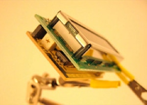
The I2C LCD Back-Pack is a small(ish) PCB that can be plugged onto the back of an LCD so that you may control it over an I2C bus.
I2C is a technology for serial communication that uses a two wire bus between to or more IC’s and was developed by Philips. I2C is used in some EEPROMs, LED drivers, Analog to digital converters and other devices. I2C is not that fast, but it is easy to use, both bit banged or with a micro-controllers I2C as a built in peripheral.
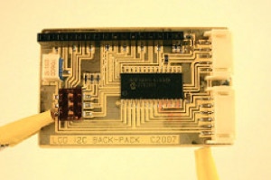
The I2C Back-Pack is based on the 23017 from Microchip. The 23017 is a port expander with 16 GPIO ports. The ports can be either input or output, you can have week pull-ups, and an interrupt signal caused by changes on either 8 pin port making up the 16 pins. Check out the spec sheet.
In this project, 8 pins are used for the 8 bit interface for the LCD, 3 pins for the control signal to the LCD and the last five are free for button input (or other output if you want).
Since I2C is bus based, devices on the bus must have addresses. To make this project more flexible I have included a surface mount switch though which the address is settable for 7 unique address.

To use the back-pack, your application must to a two step initialization.

1. The 23017 must be initialized, this sets the pins as inputs/outputs, week pull-ups for the button pins, and sets polarity and interrupt conditions.
2. Next, the LCD must be initialized. This is very typical, and covered on many web sites or the Hitachi LCD specs. This initialization adjusts, the interface size (8 or 4 bits), the curser direction, fonts size etc.


After the initialization you just send characters or commands to the display by sending them to the I2C address of the 23017 that you are using. If you’d like you can also read button inputs from the 23017.
On the Downloads page you will find the “Hello World LCD” program that initializes the 23017 and LCD plus outputs a string of text to the LCD. I wrote it for the PIC16F688. This chip does not have built in I2C, so it uses bit banged version. That part of the code is a modified version of code from an Application Note on the Microchip web site. The beautiful thing is that I have run the PIC16F688 from 4 to 20 MHz and have not had to make any adjustments in the I2C codes timing!
Parts:
U1
R1,2,3
R4*
R5
C1
C2
J1
J2
J3
VR1
SW1
Description
MCP23017
10k ohm 0603 Resistor
470 ohm 0805 Resistor
10k ohm 0805 Resistor
0.1uF 0805 Capacitor
0.1uF 0805 Capacitor
.1” SMT header female
JST Header 5pos side
JST
SMD Trimpot 10K
SMD 3 POS Switch
* Use correct resistor for your LCD LED’s current requirments.
Digikey PN:
MCP23017-E/S0-ND
S4507-ND
455-1752-1-ND
455-1753-1-ND
3361S-103GLFCT-ND
CT2193MST-ND
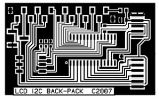
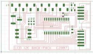
If you would like to make your own there is a one sided PCB available below.
The I2C LCD Back-Pack will work with other micro-controllers, like the Arduino or the Basic Stamp, you will just have to covert the code. If you do, drop me a line and I’ll add you code to the downloads page with a big thank you!

Copyright SpikenzieLabs 2019
