Learn :
Build Guide


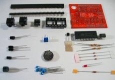
Here is a list of what you will need to build a VS. The tools at the top of the list are essential, were as the others are helpful.
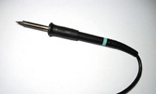
Soldering Iron:
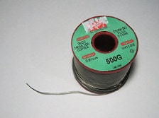
Solder for electronics: If you get the lead free type make sure that your soldering iron works with it. (Lead free solder normally requires more heat then the leaded type.)
If you are new to soldering I would recommend using leaded solder, just wash your hands after handling it. In either case get some ventilation so that you do not have to breathe the fumes.
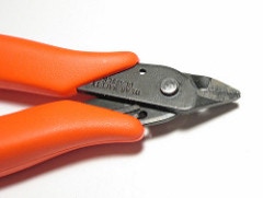
Flush cutters: Used to cut off the leads after they are soldered. Normal wire-cutters will do but these flush cutters get very close to the PCB, notice the flat area on the cutting part, and this is important so that parts do not short on the Arduino, that will be underneath.
Wear Safety Glasses: These cutters will send a lead flying across the room!
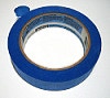
Painters tape: Used to hold the parts onto the board when it is flipped over to solder.
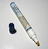
Solder flux: Used to help the solder stick better to the metal of the pads and component leads. Also, increases the surface tension of the molten solder so it flows better.
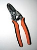
Wire cutter / stripper: Can be handy when adding jumper wires to a speaker.
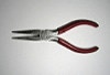
Pliers: Can be handy when bending some leads.

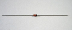
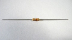
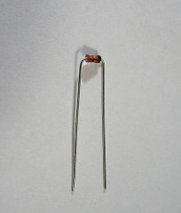
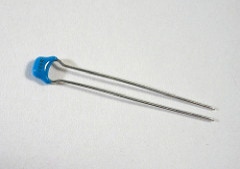
The preparation for the diodes and the resistors is the same.
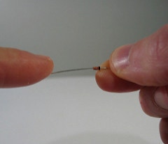
Start by holding the part tightly between two fingers. Hold it by the body, in this photo it sticks out more just so you can see it.
With a finger from your free hand, bend the lead perpendicular to the body of the component.
Do not press the part against a desk or other object, since the diodes are made of glass, they could crack if forced.
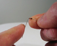
Turn the part around and bend that other lead in the same way.
Do this with all the didoes and resistors.
After the diodes and resistors are bent they should fit into PCB like this.
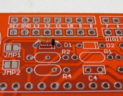
NOTE: Diodes are polarized , the black strip must match-up with the white line silkscreened onto the PCB.
Resistors may be inserted in either orientation.
I like putting them all in the same way, just because I think it looks better.
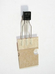
If the 3 volt, voltage regulator looks like this one you will have to straighten the legs.
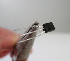
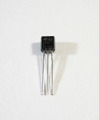
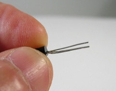
Make the legs straight, and adjust the middle one so that it is a little further back then the others.
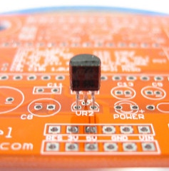
Once the legs are straight it should fit into the PCB like this.
When soldering, leave the regulator around this high off the PCB.
The male pin headers are very easy to prepare, just snip them with you cutters. For the VS you will need two with 6 pins and two with 8 pins.
If your female headers are not the correct length for your PCB then you will have to cut them to the correct length. The procedure for the female headers is a bit more difficult.
UPDATE: The VoiceShield Full kits now come with female headers manufactured to size, no need to cut !
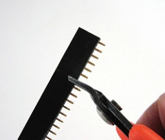
When cutting a female header, one position is always wasted.
In this photo a six pin header is being made. Notice that the snips are positioned over the seventh pin.
Wear Safety Glasses
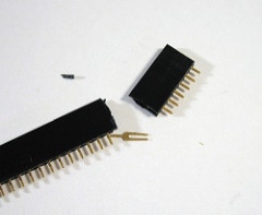
Pin header cut at the seventh position to make a six pin header.
The metal pin in this photo is the seventh pin that will get discarded.
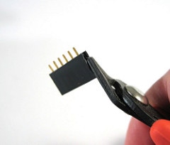
Cleaning the cut end. You can snip small pieces off until it looks good, or place some sandpaper on a flat surface and rub the cut end over it.
You can start the soldering process with any of the parts, the parts will fit in any order of placement.
But, by preference I like to solder in this order;
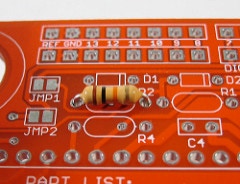
1. Resistors and Diodes: After they are pushed though the PCB, I like to tape them down from the top so they don’t fall out or move when I flip the PCB over. You can also bend the leads to hold them in but I don’t think that works as well. Diodes only go in one way !
NOTE: Diodes are polarized , the black strip must match-up with the white line silkscreened onto the PCB.
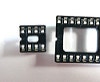
2. Socket headers: There are two socket headers, one eight pin and one 28 pin. Simply push them though, sometimes they hold themselves in, other times you will need to bend a pin or use a little tape. Note: The end with the notch for pin 1, goes toward the left, when the board is upside right (you can read the white silk screening normally). I like to start by soldering the two pins on opposite sides. This way if the socket isn’t nice and flat against the PCB, you can just reheat one or both pads and push until it is. After it is flat, you can rapidly solder the rest of the pins.
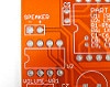
Note the notches on the left.
Match the notches with the bump in the printing.
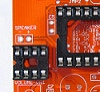
The sockets should look like this.
3. Small capacitors: Starting with the small capacitors (small-blue ones), I like to solder one lead at a time, then flipping the board upside right straighten them and solder the remaining leads. These capacitors may be inserted in any orientation.
4. Large capacitors: The remaining capacitors are the electrolytic type, these ones look like little barrels and have their values printed on them and a white stripe down a side. This white stripe also sometimes has a “-” character printed with it, which shows you that the pin on that side is the cathode (the pin that goes on the lower potential side ie. negative voltage). This is really important, since these capacitors will only work correctly if they are inserted with the right orientation. To solder these just push them all the way into the PCB, with the “-” pin lined up with the “-” printed onto the PCB.
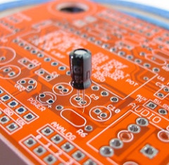
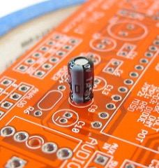
Note the “-” on the PCB and the white stripe with the “-” on the capacitor, they must matchup .
Before you solder the capacitor push it all the way onto the PCB.
5. Audio jacks: There are two 3.5mm style audio jacks on the VS, if your kit has two different audio jacks then the one with five (5) pins must go into the “audio out” holes and the jack with three (3) pins must go into the “audio in” holes. If your kit has two jacks that both have five pins then they can go into either set of holes.
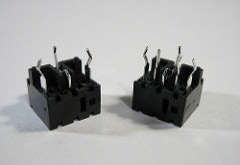
UPDATE: All VoiceShield kits now come with two five pin audio jacks.
On the left, audio jack with 3 pins, this is for the “Audio In”.
On the right, audio jack with 5 pins, this is for the “Audio Out”.
(If you have two with 5 pins use either one.)
6. Variable potentiometer and voltage regulator. The POT only fits in one way so just solder it in place. Do not push the voltage regulator all the way onto the PCB, ie leave a bit of space 1/4” to protect it from over heading during soldering.
Solder the power LED with the long lead in the pad with the “+” symbol.
7. Pin Headers: Start with the male pin headers. These go into the Arduino, so the best way to solder them is to plug them into the Arduino then lower the VS over them. Make these pins go though the holes with the arrows. Next, solder on the female headers, make them stand up like the ones on the Arduino.
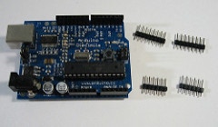
Start with your Arduino and male pin headers.
Next, place the male headers into the Arduino’s female headers.
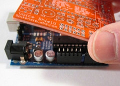
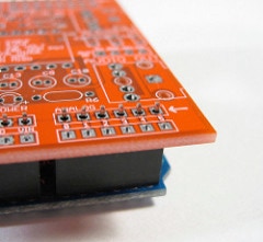
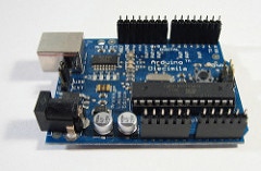
Slip the VS PCB onto the pins. This is an easy way to make sure the VS is alined with the Arduino pins, so that it is easy to take-off and put-on to the Arduino.
Make sure that the white arrows point to the pins sticking through the PCB then solder.
8. Speaker: If you want to install the on board speaker, find and solder two small pieces of wire onto the speaker terminals then solder the other ends onto the two speaker pads marked Speaker + -. You could also use, pin headers here to make changing the speaker more easy.
9. Insert the LM386 Amp and the ISD4003 ChipCorder® into the socket headers on the VS. With the VS positioned so you can read the name, insert both chips with the small dot near pin 1 on the left side. The pins of these chips may have to be squeezed a little to get them in. Only handle the ISD chip by the edges and leave it in the static safe package until you are ready to install it onto the the VS.
Caution: Always disconnect the power (or unplug the USB if USB powered) first before making or undoing any connection to the VoiceShield. The ISD4003 is easily damaged if mishandled.

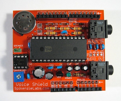
10. Congratulations you should how have a completely built VoiceShield.
The next step is to load some audio into the VoiceShield. Take a look at the VoiceShield Software page to download; the VoiceShield Programmer (for your computer), sample audio files and demo Arduino sketches to run the VoiceShield. I recommend starting with the Basic Phrase Talk Sketch, since it does not use any other hardware.
Copyright SpikenzieLabs 2019