Due to the wild popularity of one of our simplest kits, (The Original Drum Kit Kit) we have gone back to the drawing board, and expanded on this already amazing product. You're big time into Arduino? Good news, this flavor of the SpikenzieLabs Drum Kit Kit doesn't monopolize your Arduino. The 'Arduino Guts' are on-board and dedicated to your new drum set. New to Arduino? We've made this kit as simple and straight forward for newbies. Order it as a kit, or pre-assembled & programmed and you'll be tapping out beats as soon as your pads (not included) are connected.
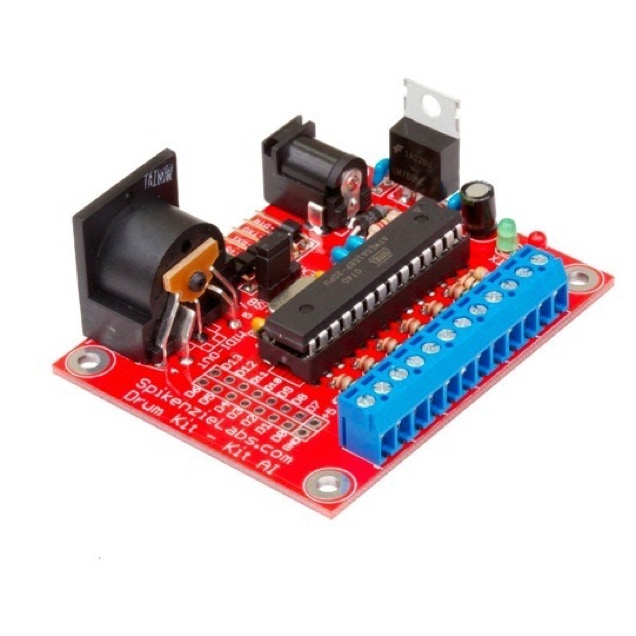
The A.I. version of the Drum Kit Kit is an 'All Included' version of the original. On board Ardunio, MIDI out, and an FTDI connection out to your computer. For those of you who don't know what an FTDI connection is, just think of it as a connection for a 'Special USB Cable' that connects the device to your Mac/Windows PC/Linux computer in the same way you would connect a printer. Sounds simple? Well, it is!
1. On board ATmega (frees up your Arduino for other projects).
2. Screw terminals for the drum pad connections (makes changing pads easier).
3. On board Din-5 MIDI-out jack (Use the DKKAI, with your other MIDI equipment).
4. FTDI compatible 90° pin header (makes it easy to program or use our Serial to MIDI software on your computer).
5. DC 2.1mm power jack (power the Drum kit while “one the road”).
6. All the ATmega digital pins are brought out in two rows of connectors with standard 0.1” spacing. With, +5 volts and ground (make your own accessories, selector buttons etc ...).
7. Four corner mounting holes (Build the Drum Kit into a project box and mount it).
8. On board voltage regulator.
9. Power selector jumper for USB (via optional FTDI cable) or DC power jack.
With the Drum Kit Kit AI, you get to DIY your own drum pads. (See below for tips & techniques). Once soldered, and pads connected, upload the Sketch, using the Arduino IDE, (As if you were programming your Arduino) and test it out.
Wait! What is the Arduino IDE (integrated development environment)? Think of it as a word processor that let's you print your document to a circuit board, rather than a printer. Once the Drum Kit Kit AI receives the program that you've sent over, it starts to work. Thanks to our Serial to Midi software you will have the Drum Kit Kit AI running with your computer along side your audio software.
We've documented the program in such a way that assigning notes to your drum pads is a snap. Depending on what you've made your pads out of, you may need to tune the trigger sensitivity. This is easily adjusted, with a little trial and error, you'll have them functioning just as well as a 'store bought' drum kit.
If you've got a Drum Synth with a Midi in? Plug the DKK AI right in, and start playing. No computer required, other than to assign notes and set other settings like velocity and trigger sensitivity.

I love this kit, it comes in a anti-static bag choc-o-block full of parts! Even though there are lots of parts, it is quite easy to build.
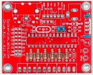
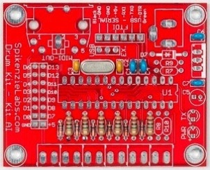
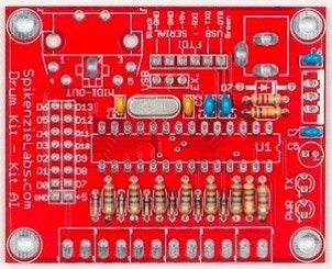
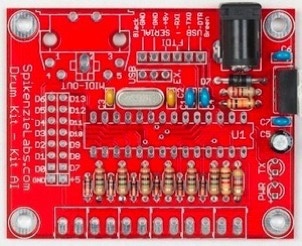
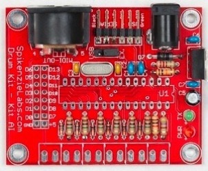
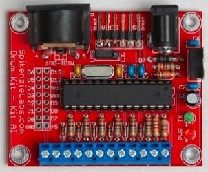
Below is an illustration with all of the parts and values noted. If you are familiar with electronics and have built kits before you can use simply check the illustration to see where the parts go and start soldering.
For those of you that are new to electronic kit building, there are step by step instructions below.
Drum Kit - Kit AI: Parts placement
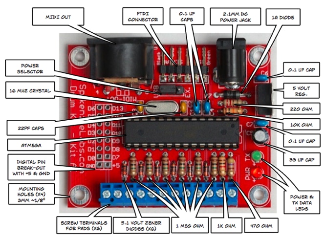
Reference illustration for the Drum Kit Kit AI’s part placement.
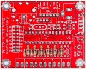
One of the great things about this kit is that all the parts are through hole, spacing is good and it really doesn’t matter in which order you solder the components. Below is just a suggestion for the sequence that we used to build ours. As long as you have the parts in the correct locations and parts like the diodes are in the correct orientation, you should have no problem.
Parts that only go in one way, are marked in red with a “ NOTE” .
Install the six 1 Meg Ohm resistors and zener diodes.
The 1 Meg Ohm resistors are [Brown - Black - Green - Gold].
Solder the six small zener diodes in place (redish / pink glass parts with a black stripe on one end).
NOTE: These diodes must be installed with the black line on the diode lined up with the line printed on the PCB.
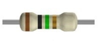
1 Meg Ohm
470 Ohm
10k Ohm
1K Ohm
220 Ohm
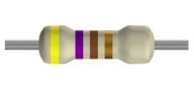
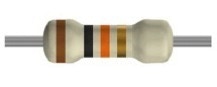
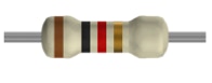
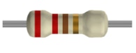
Resistor illustrations from Sam Engström’s web page: samengstrom.com
Install the four 0.1uf capacitors.
These are the little blue ones.
Install the 16 mhz crystal and the two 22pf capacitors.
The capacitors are the small mustard colored ones, and the crystal is the long silver can.
Install the remaining resistors, matching them to the spaces listed below.
R9 = 220 ohm [Red - Red - Brown - Gold]
R7 = 10k ohm [Brown - Black - Orange - Gold]
R8 = 1k ohm [Brown - Black - Red - Gold]
and
R10 = 470 ohm [Yellow - Purple - Brown - Gold]
Install larger diode and DC power jack connector.
NOTE: This diode is black with a silver ring on one end, the silver ring must match the white line printed on the PCB.
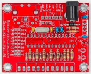
Install the 5v voltage regulator and the remaining capacitor.
NOTE: The back, metal part of the voltage regulator matches the white area printed on the PCB and goes toward the outside of the PCB (see photo).
The capacitor is the small round black barrel.
NOTE: It is important that the white line on the capacitor with “-” printed on it match up with the hole “-” on the PCB.
Install the DIN-5 connector (MIDI-OUT), the FTDI 90° pin header and the power selector header. (The small two pin jumper goes on this header.)
Solder the two LEDs into place.
NOTE: The long leg on the LEDs must go into the hole on the PCB marked with a “+” printed on the PCB.
Arrange the six screw terminals by sliding the edge of one into the edge of the next.
NOTE: Make sure that both the top and bottom ridges have slide into each other.
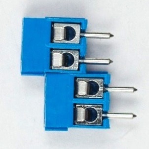
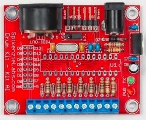
Solder the screw terminals to the bottom edge of the PCB with the holes to insert the wires pointing away from the resistors.
If they do not fit well, check to make sure they have all locked together in the previous step.
Solder the 28 pin socket onto the PCB and insert the ATmega chip into it.
NOTE: Make sure that the notch on the socket, printed onto the PCB and the chip all line up. Here pointing toward the right.

There are a lot of options for building your drum pads. You can make them out of wood, metal or other objects. On our How to make Drum Pads page , there is a detailed description of how to build them using sheet metal, mouse pads and packing foam.
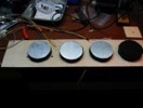
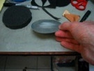
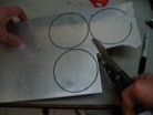
Cutting disks to give the drum pad some body.
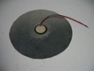
Sanding so that the glue used for the piezo holds more strongly.
Gluing the piezo on with two-part epoxy.
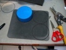
Making tops for the drum pads out of neoprene mouse pads.
Drum pads mounted onto a board. Spray adhesive was used to glue the layers together.
See the full instruction on the original How to make Drum Pads web page.

The new Drum Kit - Kit AI and older Drum Kit -Kit both use the same Arduino sketch (a sketch is the name given to an Arduino program). The Drum Kit - Kit web page has more details about using the sketch. You can download the sketch here: DKKAI Downloads Get the latest Arduino software from Arduino.cc
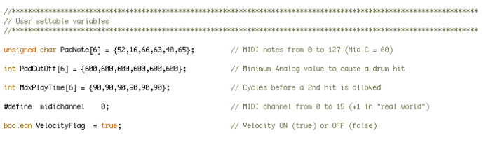
User changeable setting in the Drum Kit Arduino Sketch. Find more info on the original Drum Kit Kit web page.
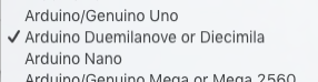
In order to compile and upload a replacement sketch to your drum kit the Arduino IDE has to know which style of Arduino the drum kit is.
In the Arduino IDE under the tools menu, choose the following;
Board: Arduino Duemilanove or Diecimila
Processor: ATmega 328 (at 16 mhz)

Using the Drum Kit - Kit AI is pretty easy. You start by deciding how and what you are going to connect it. Are you using it with a USB -Serial cable or the MIDI-out port? Are you powering it over USB or with a AC adaptor? etc ...
USB - Serial cable or MIDI-out port:
If you are using the Drum Kit - Kit AI with the USB - Serial cable then you will need to download the Serial to MIDI converter software. You will also need to use audio software on your computer, such as Apple’s Garage Band etc... Check the Serial to MIDI Converter web page for instructions on how to set it up on your computers OS.
USB - Serial cable:
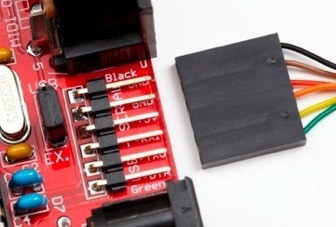
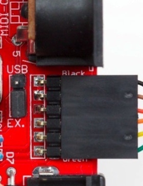
Connect the USB - Serial cable to the six pin head on the rear of the Drum Kit PCB (it’s best to connect this end of the cable before plugging the USB end into your computer). Make sure to plug the six connector end into the Drum Kit with the black and green wires on the correct sides (Black and Green are printed on the PCB).
MIDI-Out port cable:
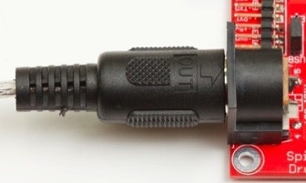
Using the MIDI jack is simple, just connect a MIDI cable from the Drum Kit’s MIDI out port to your equipments MIDI-IN port.
You can also us the MIDI-Out port to connect to your PC by using a MIDI to USB converter such as M-Audio’s MIDISPORT Uno .
See the box below for setting for MIDI baud rate settings.

Using the Drum Kit - Kit AI MIDI-out port:
The DKKAI has a built on MIDI-out port, to use it, make sure that the sketch that you upload onto the Drum Kit - Kit AI has the serial board rate set to 31250. (This line is in the code section called “void setup”.)

Note : If you are using the DKKAI with the FTDI USB - Serial cable and our Serial to MIDI software, do not choose 31250 as your baud rate, there is a bug with the Serial to MIDI converter or part of the Java serial which prevents the SM converter from working correctly.
The Drum Kit - Kit AI can be power from the USB - Serial cable or from a 2.1mm DC power adaptor. The Drum Kit - Kit AI must be used with the power selector jumper. Simply slid the jumper onto the two pins marked USB or EX.
Power from USB - Serial cable:
The USB - Serial cable can provide the +5 volts needed to run the drum kit. In this case the power supply section of the Drum Kit does not function, the voltage regulation is done by the USB bus. Note: USB only provides up to 500ma of power, so if you are connecting custom circuitry to the digital pin connectors or the +5v and GND, make sure to not exceed this limit.
Power from a DC Power Adaptor:
With the power selector jumper in the Ext. position the Drum Kit will use the 2.1mm DC power jack. This jack will accept a center positive 2.1mm power connector, from 7v to ~ 15v. The maximum current draw is 1 amp.
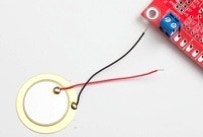
The Drum Kit - Kit AI can be with up to six drum pads. The drum pads are essentially disks that have piezos glued to them. The piezos have two wires coming of of them, a red and a black one.
Connecting piezos:
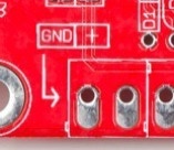
The bottom edge of the Drum Kit - Kit AI has six sets of two screw terminals. Each screw terminal set is used for one drum pad. It is important that the red wire from the piezo goes into the screw terminal on the right side of each terminal and the black wire goes into the left side. When you extend the piezo wires be careful to note which is the red and which is the black.
Copyright SpikenzieLabs 2019