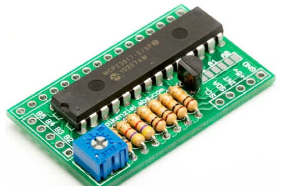
This Project is a re-Make of the I2C Back-Pack , but this version is available from the SpikezieLabs Store as an easy to solder thought hole kit. And, also expands on the flexibility by including pins for an SPI version.
I2C summary:
I2C LCD Interface allows you to connect an LCD to a micro controller with only two wires.
A. You would like more pins to be available for another use, normally an LCD interface requires a minimum of 6 pins.
B. You are already using the serial port (or don't have one) to run a serial LCD display.
C. You would like to make a control panel. Not only does it let you drive a display, but there is also the possibility of five button inputs!
• Use only two wires from your micro-controller
• Use up to seven I2C LCD interfaces on the same I2C bus.
• Use other I2C devices such as EEPROMS, Thermometers, LED drivers etc ...
• Easily wire a five button input pad, like a control panel. (With seven I2C LCD Interfaces you could have 35 buttons in all!)
• Free up your serial port for other another use.
The I2C LCD Interface can be used with the Basic Stamp, the Arduino, a Microchip Pic, or any other micro-controller that has built in or a bit banged I2C interface.


The I2C-SPI Interface connected to an LCD Display. Note that the display is upside down in this photo and that pin 1 on the LCD goes into the pin on the top right hand side of the interface.
This the the I2C Interface in it’s “working” position, but with no display attached. Note that unlike the other parts, this header is inserted from this side of the PCB and gets soldered on the other.
With the Arduino you use the Wire library which contains the I2C commands. To get the basics on how to use the I2C-LCD Interface download the demo Arduino sketch
I2C_LCD_Demo.pde.zip . This sketch is a "building block" for your own sketches. It contains the basic functions to write I2C commands to the board and thus the display. When you load and run this sketch it will display a message and a three digit counter. Also, if you wired up some buttons to the button pins it will display a message when you press one.
HOOK-UP:
SIGNAL I2C LCD BOARD - ARDUINO
Ground GND GND
VCC 5V 5V
SDA** SDA Analog 4
SCL** SCL Analog 5
The buttons (if used) are wired with a normally open (NO) switch to ground. (Pressing the button will contact the ground signal) J3 on the PCB has an extra ground and pins for buttons 1 to 5.
** I2C communications require a pull-up resistor on both the SCL and SDA lines. There must be a 4.7k through 10k ohm resistor on both the SDA and SCL pulling them up to VCC. If you are using other I2C devices (or other I2C LCD Interfaces) use only one set of pull-up resistors.
Pull-up resistors are not included on the I2C-SPI LCD board, since; they are not required when the board is used with the SPI interface, only one set of resisters is required for the I2C bus (if you where to use more then one board there would be too many), and it gives you more flexibility to adjust to your I2C bus.
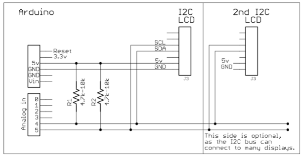
A simple schematic to illustrate, how to connect pull up resistors to the I2C bus. The right side is to show you that the bus can have one, two or more I2C devices on the same bus.

If your project in partially on a bread board then it is very easy to include the pull up resistors (left photo). If not you could make an adaptor wire that has the pull-ups built into it (right photo).
1. Disconnect the power and hook-up the Arduino and the I2C Board as described above.
2. Set your I2C address. (Up to 7 I2C Boards and be used on the same I2C bus.)
Look in the define section of the Ardunio sketch for this line
#defineMCP23017B00100xxx
the "xxx" is your board's changeable I2C Address. (default is 000)
Use the dip switch on the I2C board to modify the address. Switch position 1 is the LSB, rightmost "x" above.
3. Power the board and upload the sketch to the Arduino.
4. You should see a message and a counter on your LCD. If not Don’t Panic, turn off the power, and check your work. If you didn’t find any mistakes, power it back up, you probably need to adjust the contrast POT with a small screw driver (blue square on PCB) to see the display properly.
5. If you hooked up buttons and are pressing one, you should also see that message.

An early prototype of the I2C LCD Interface that I used to program a MIDI instrument’s notes and settings.
To use the I2C-SPI Interface as a SPI device, a different port expander is required. The SPI version uses the Microchip MCP23S17, note the “S” in the name.
Building the board for the SPI version is exactly the same as that for the I2C version. The only difference is the version of the 28-pin dips used.
Wiring up the SPI version to your micro-controller is different. To use the SPI interface four I/O pins are connected, SI, SCK, SO and CS. These pins are marked on the PCB.
Since the transfer speed of a SPI interface can be much faster then I2C, when using the I2C-SPI LCD Interface in SPI mode, small delays may have to be added after sending a command to the display. This is because the Hitachi display has long execution times for some commands, for example “Clear display” could take around 1.7ms. If there is no delay or the delay is too short and another command or text is sent to the display after the clear display, junk or cut “text” could result on the display.

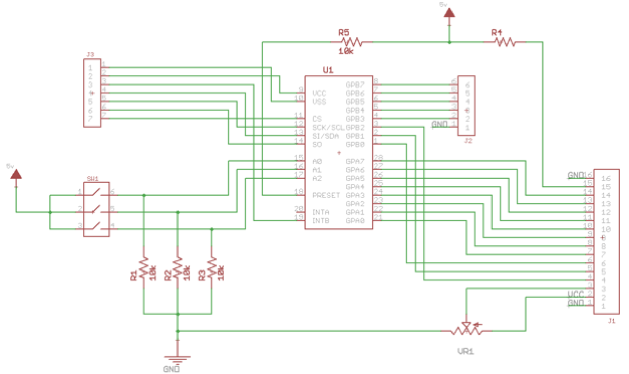
Schematic.
Copyright SpikenzieLabs 2019

