The Message Pump USB and the new Message Pump Serial are now both coming preloaded with firmware version 2.
Message Pump FWv2 adds enhanced features, more choices for communications, better user control and a thinner package.
New features with Message Pump Firmware V2.
1. More baud rates
2. Optional Splash screen
3. I2C slave interface
4. 80 character RX buffer
5. Dual active Serial and I2C Interface
6. Thinner module
7. User resettable
8. User settable command character


Like the previous Message Pump the basic usage is the similar whether you are using the USB, Serial or I2C interface.
To display text all that is required is to send ASCII characters to the display. The text will start to display from the top left most position and fill the spaces toward the right, skipping down each line as they are filled and finally starting over at the top left position after the entire display is filled.
The new and updated features are explained below. This is a listing of the updated commands for Message Pump firmware v2. Some of the commands are the same, some are completely new and others have additional options.
Table 1. Instruction message format. Commands are always 3 bytes long.
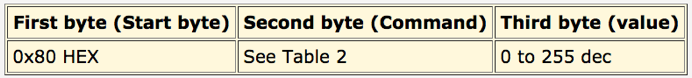
Table 2. Message Pump instructions and options list. (* default value)
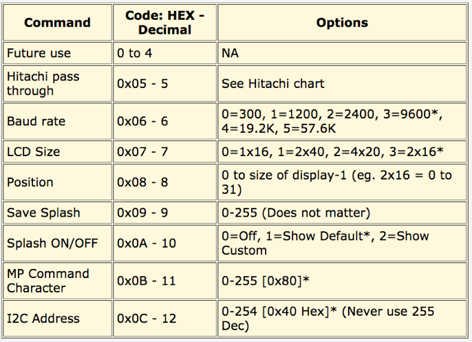
Table 3. Standard Hitachi 44780 LCD instructions list.

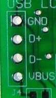
The USB hook-up for the Message Pump USB is still the same as the original Message Pump . You either use a cable from your computer with a USB Mini-B connector or wire directly onto the VBUS, GND, D+ and D- pins on the left side of the Message Pump.
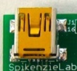
Mini-B USB connector
Solder wire directly to PCB
With either the USB or Serial version of the Message Pump, you have the option of also using the I2C interface. You may use just the main interface or both the main interface and the I2C, or just the I2C.
Hook-up is done by wiring the SDA and SCL pins (show below) onto the I2C bus of the master I2C device. Since the Message Pump Serial will probably be used more often with a micro-controller the R5 and R6 I2C pull-up resistors are populated. To use I2C with the USB version you will have to either solder on your own resistors, or use other resistors on your I2C bus.
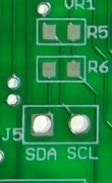
I2C connection, with pads for R5 & R6 required for I2C pull-up resistors.
If you are using an Arduino (Duemilanove or Diecimila style board) and the Wire Library you would connect Arduino’s analog pin 4 to the SDA pin and analog pin 5 to the SCL pin.
To use the Message Pump with I2C before each byte of data you must first send the seven bit I2C slave address. This is part of the I2C standard, it is required so that different slave devices on the same I2C bus can tell when the master device is “talking” to them. The factory default slave address for the Message Pump is 0x40 HEX (64 decimal).
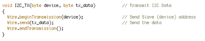
Sample of Arduino code used to send I2C slave address and then the data byte.
If you have other I2C devices on the bus that have the same I2C slave address, you will have a conflict. The I2C address is stored in the Message Pump’s EEPROM and is user settable and since it is stored in the EEPROM. It will remain set until the device is “Reset” or changed again by the user.
To change the address you send the change I2C address command to the Message Pump then the new address. Eg. This is how it would look to reset the address to decimal 32 (b’0010 0000). [ 0x80,0x0C,0X20 ] Where 0x80 is the Message Pump command start byte, the 0x0C is the change I2C address command and finally the 0x20 is the number 32 Dec in hex.
NOTE : the slave address is 7 bits, and uses bits 7 to 1 of an eight bit byte, but not bit 0, so the address can never be 0xFF (255). The 0 bit is used to tell the device if it is being written to or read from and is part of the I2C standard.
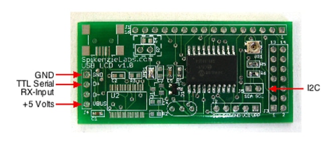
The serial version of the Message Pump uses the auxiliary USB connector. GND is still ground, VBUS is +5 volt input, but D+ is used as a TTL Serial RX (Input pin), and D- is not used.
NOTE : You can not connect serial to the D+ pin if you have a Message Pump USB.

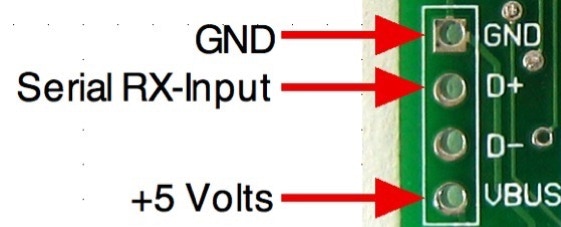

Pin-out of the Message Pump Serial.
Set the baud rate of your microprocessor or computer to match the baud rate of the Message Pump. The default rate is 9600 bps.
( NOTE : The Message Pump uses 5 volts TTL signals, don’t connect it directly to your computers serial port with out a level shifter. If you want to connect it to your computer you can use the popular MAX232 level shifter from Maxim.)
When you first power-up the Message Pump the default is to show you the Message Pump splash screen. This splash screen is actually a series of 3 screens, first it displays “Message Pump” and firmware version, then the current baud rate and finally, the current I2C address. If you change the setting such as the baud rate or I2C address the updated values will be displayed.
Optionally you can turn off the splash screen altogether or replace it with your custom splash screen.
It order to save a new custom splash screen into the EEPROM you first send the “save splash screen command”. This would be 0x80, 0x09, 0x00 (Start byte - Save Splash - zero). Then the next 16 characters that you send will be saved into the EEPROM as the custom splash screen. Note: you can send more then 16 characters, but the slash message will get cut off at 16, on the other hand if you send less then 16 characters then the Message Pump will keep waiting until it gets 16 characters.
NOTE: To see the your custom splash screen you must set the Show Splash Screen to option “2”. The default setting is “1”, show the standard Splash screen and ON.
You can reset the Message Pump to its factory default settings using this procedure.


1. Turn off the Message Pump.
2. Short the VPP pin to ground. (Use a wire to connect this pin to GND)
3. Power ON the Message Pump.
4. You will see a message “Resetting”, after a moment you will see the default splash and info screens appear.
5. Power OFF the Message Pump.
6. Undo the connection from VPP to ground.
7. The Message Pump is now reset.
NOTE: This does not replace the custom Splash Message. To replace the custom message you simply re-save a new splash message over it.
Normally it is recommended that you not change the default start byte from 0x80. But, if you have an application were this character causes a conflict, you may change it.
The procedure to change the command character is similar to changing the I2C address.
To change the command character you send the “Change Message Pump Command Character” command to the Message Pump fallowed by the new character. Eg. This is how it would look to reset the Command Character to 0x75. [ 0x80,0x0B,0X75 ] Where 0x80 is the (OLD) Message Pump command start byte, the 0x0B is the change Command Character command and finally the 0x75 is the Command Character.
NOTE: Any new commands that you send to the Message Pump must now start with the new command character, until it is changed again or the Message Pump is reset.
Copyright SpikenzieLabs 2019

