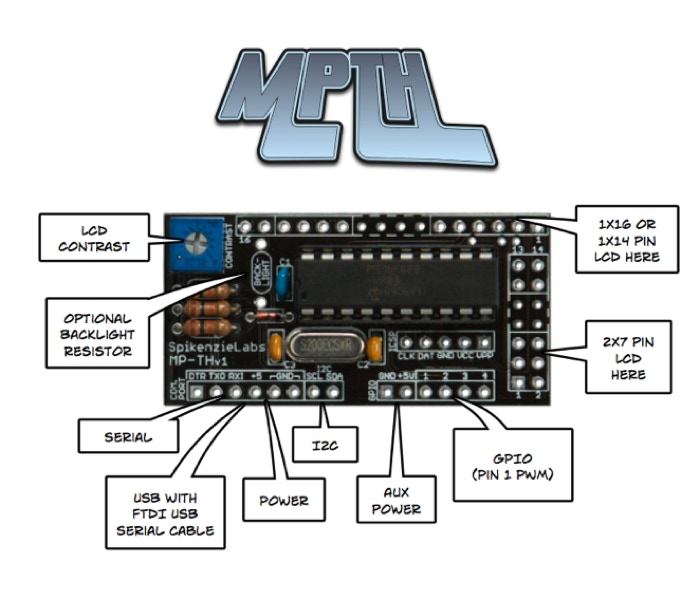
The MPTH is an LCD back-pack which makes it easy to connect an LCD to either your microprocessor project or your computer.
This is an updated version of the original Message Pump but now in an easy to solder through hole kit.
The new MPTH some really great features:

• Supports multiple size character LCD displays (1x16, 2x16, 2x40, 4x20)
• Has pin-outs for LCDs with either 1x14(16) or 2x7 pins
• 80 Character buffer
• Four GPIO pins. (General purpose input / output pins)
• One PWM (Pulse width modulation) pin
• Baud rates up to 115.2k (300,1200,2400,9600,19.2k,57.6k,115.2k bps)
• USB Connectivity (with FTDI USB cable)
• TTL Serial
• I2C
• User settable I2C address
• User settable command character
• User settable auto output of GPIO changes
• Dual simultaneous interface Serial and I2C (Both on all the time)
• User settable Splash Screen
• Optional echo of display text to serial port
• Easy to turn, robust trimer pot for contrast
• Easy to easy to build kit, with through hole parts
• “Junk” command watch dog timer
• Small size
• Electronic Back-light intensity control (version 3 only)


To display text all that is required is to send ASCII characters to the display. The text will start to display from the top left most position and fill the spaces toward the right, skipping down each line as they are filled and finally starting over at the top left position after the entire display is filled.
Hooking up the MPTH to an Arduino using serial is super easy! If you just want to display text you just need one wire! (Plus power of course).
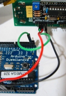
Minimum requirement to use the MTPH with a serial connection to an Arduino. Here the Arduino TX (Digital pin 1) goes to the RXI (Receive data Input) pin of the MPTH.
Set the baud rate of your microprocessor or computer to match the baud rate of the Message Pump. The default baud rate is 9600 bps.
( NOTE : The MPTH uses 5 volts TTL signals, don’t connect it directly to your computers serial port without a level shifter. If you want to connect it to your computer’s serial port you can use the popular MAX232 level shifter from Maxim.)
Hook-up is done by wiring the MPTH’s SDA and SCL pins onto the I2C bus.
Note: If you have multiple I2C devices on the I2C bus and already have pull-ups else where, you may not need the pull-up resistors R2 and R3 on the MPTH.
If you are using an Arduino (Duemilanove or Diecimila style board) and the Wire Library you would connect Arduino’s analog pin 4 to the SDA pin and analog pin 5 to the SCL pin.
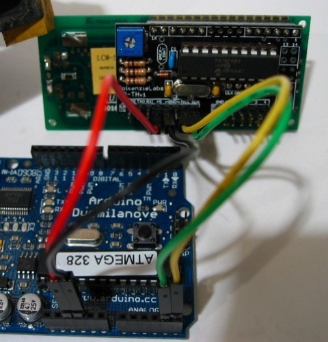
Arduino I2C hook-up: All that is required is power and two wires one for SDA from Analog pin 4 and another for SCL from Analog pin 5.
To use the MPTH with I2C you must first send the seven bit I2C slave address. This is part of the I2C standard, it is required so that different slave devices on the same I2C bus can tell when the master device is “talking” to them. The factory default slave address for the MPTH is 64. If you are using other I2C devices such as a temperature sensor, port expander or other MPTHs, you may need change the I2C address. The MPTH uses 7-bit I2C addressing, which gives a total of 112 address possibilities (16 address are reserved by the I2C standard). More about I2C here .
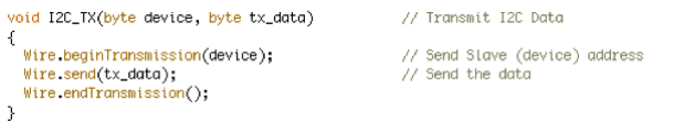
Sample of Arduino code used to send I2C slave address and then the data byte.
The easiest way to use the MPTH with your computer is to get the FTDI USB to Serial cable . The MPTH pin-out matches this cable, so using it is simply a matter of plugging the cable onto the MPTH, then using your favorite terminal software (or your own software) to send text to the display.
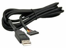
FTDI USB to Serial Cable. Either the 5 or 3.3 volt version will work.
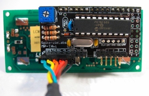
Here the FTDI USB to Serial cable is plugged onto the MPTH. Note that the green wire is on the left and the black (ground) wire is on the right and is connected to the pins marked GND on the MPTH. The FTDI cable provides both bi-directional serial and power to the MPTH.

The MPTH can receive two types of data, character data or commands.
Character Data:
Character Data is simply ASCII text and is sent one byte at a time to the MPTH. If the characters that the MPTH receives are normal text (letters, numbers and symbols) the text will be displayed on the screen.
Commands:
Commands to the MPTH are used to change settings. Settings include the size of the LCD, the baud rate of the serial port, clearing the display etc... (Below is a full list of MPTH commands.)
All commands sent to the MPTH must always be three bytes long. The first byte is the command start byte. This lets the MPTH know that it is receiving a command as opposed to character data. The second is the command (see list below). And, the third is the setting value.
How to send commands:
How you connect to the MPTH will determine how you send commands to the MPTH. Both character data and commands arrive at the MPTH in the same manner. As far as the MPTH is concerned all data that it receives goes into a buffer and are dealt with when the MPTH is not busy receiving other data. No need to worry about the MPTH slowing down though, it runs through four million lines of code per second!
To display text from an Arduino use this in your sketch;
Serial.print(“Your text here”);
or to display a number
Serial.print(YourVariable, DEC); // using the ,DEC sends the YourVariable and formats it as a decimal numb.
But if you want to send a command it would look like this:
// Example to set the baud rate to 57.6k
Serial.write(128); // 128 is the command start byte
Serial.write(6); // 6 is the command to change the serial baud rate
Serial.write(5); // 5 is value setting for 57.6k baud
Over I2C:
Connecting MPTH to an Arduino over I2C is a great option when you are using the Arduino’s serial port for another connection. See the demo sketch below for more info.
Arduino Serial Demo: MPTHSerialDemo.pde.zip
Arduino I2C Demo: MPTHI2CDEMO.pde.zip
Using the MPTH with a computer:
PC:
To use the MPTH with a PC for text display you could simply use HyperTerminal with the COM port set to your MPTH’s baud rate 8N1 (eight bits, no flow control, one stop bit.) HyperTerminal isn’t good for sending commands to the MPTH. A better choice is X-CTU from DIGI the makers of the popular XBee modules.
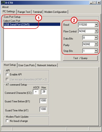
1. Select your MPTH USB to serial adapter from the list of serial ports.
2. Set the baud rate to match your MPTH, and flow control to none, data bits to 8, parity to none and stop bits to 1.
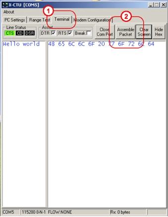
Using X-CTU with the MPTH:
Next:
1. Click on the Terminal tab.
2. Click on the Assemble Packet button.
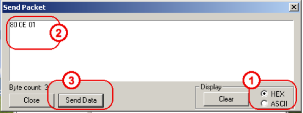
This is the window that opens to send a packet.
1. Click on HEX. This will make sure that the commands are sent and not text strings.
2. Type the command in HEX
3. Click once on the Send Data button.
Macintosh:
A great serial port terminal application for the Mac is CoolTerm by Roger Meier. You can use CoolTerm to both send text or commands the MPTH.
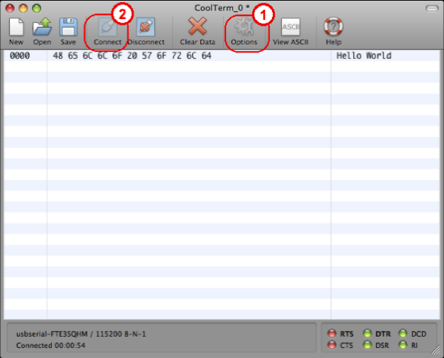
This is CoolTerm’s main window. To send a command to the MPTH, follow these steps.
First:
1. Click on Options. Set the baud rate, and other communications setting here.
2. Click on connect.
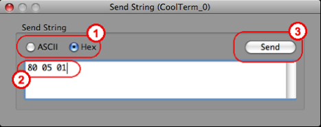


Then choose “Send String” from the Connection Menu or simply press “Apple” and “T” on the keyboard. In the window that appears;
1. Click on Hex.
2. Type the command you want to send using Hex notation.
3. Click on the Send button.


Table 1 below is a complete list of MPTH commands with descriptions.
Note: Commands are three bytes long, Command Start Byte (default is 128), Command Code, Setting value.
1. ° Setting will be saved to EEPROM and used every time the MPTH is powered up until either the settings are changed again or the MPTH is reset.
2. [ value ]* denotes a factory default value.
3. Back-Light control only on new v3 board
Note:
The numbering used in the MPTH Command chart (Table 1) is a mix of decimal numbers and Hex numbers. Hex numbers in the chart start with the 0x prefix. This prefix is used in some programing languages, and is used here to help you distinguish between decimal and Hex numbers.
The Hex numbers are included in this chart as they are needed if you want to send commands to the MPTH with terminal software.
Do not type the 0x in front of a Hex number in your terminal software.
Table 2 (at right), is a small list of decimal numbers with Hex (Hexadecimal) and binary equivalents for your convenience.

Table 2: Decimal numbers with Hex (Hexadecimal) and binary equivalents.
Custom command: Changing the Start Byte
Normally it is recommended that you not change the default start byte from 0x80. But, if you have an application where this character causes a conflict, you may change it.
The procedure to change the command character is similar to changing the I2C address.
To change the command character you send the “Change MPTH Command Character” command to the MPTH followed by the new character. Eg. This is how it would look to reset the Command Character to 0x75. [ 0x80,0x0B,0X75 ] Where 0x80 is the (OLD) MPTH command start byte, the 0x0B is the change Command Character command and finally the 0x75 is the new Command Character.
NOTE: Any new commands that you send to the MPTH must now start with the new command character, until it is changed again or the MPTH is reset.

I2C: Changing the I2C Slave Address
The I2C address is stored in the MPTH’s EEPROM and is user changeable. It will remain set until the device is “Reset” or changed again by the user.
To change the address you send the change I2C address command to the Message Pump then the new address. Eg. This is how it would look to reset the address to decimal 32. [ 0x80,0x0C,0X20 ] Where 0x80 is the MPTH command start byte, the 0x0C is the change I2C address command and finally the 0x20 is the number 32 Dec in hex.
NOTE : the slave address is 7 bits, and uses bits 7 to 1 of an eight bit byte, but not bit 0, so the address can never be 0xFF (255). The 0 bit is used to tell the device if it is being written to or read from and is part of the I2C standard.
Splash Screen: Intro
When you power-up the MPTH you will see the splash screen. This default splash screen is actually a series of screens, first it displays “MPTH” and firmware version, then the current baud rate and finally, the current I2C address. If you change a setting such as the baud rate or I2C address the updated values will be displayed.
Optionally you can turn off the splash screen altogether or replace it with your custom splash screen.
Splash Screen: Using a custom Splash Screen Message
To save a new custom splash screen into the EEPROM you first send the “save splash screen command”. Then the next 16 characters that you send will be saved into the EEPROM as the custom splash screen. Note: you can send more then 16 characters, but the splash message will get cut off at 16, on the other hand if you send less then 16 characters then the Message Pump will keep waiting until it gets 16 characters.
NOTE: To see the your custom splash screen you must set the Show Splash Screen option to “2”. The default setting is “1”, which will show the standard Splash screen.
GPIO Port:
The GPIO port, is a general purpose input output port. This means that the pins may be configured as either inputs or outputs. For example, inputs could be used to read button presses and outputs could be used to light LEDs.
GPIO Set-up: Step 1
The first step in setting up the GPIO port is deciding which pins of the GPIO port are going to be inputs and which are going to be outputs. This is changed by setting the GPIO TRIS register, by sending a value with the GPIO TRIS command, where a bit set to “1” is an input and a bit cleared to “0” is an output. (The factory default is set to all inputs.)
Using the Table 2 of Decimal, hexadecimal and binary numbers, you can see that if you wanted to set the first two pins (GPIO 1 and 2) to inputs “1” then you would send the value of 3 (which is binary 00000011). This would make the first two bits set to “1”, which are inputs.
Set-up: Step 2
Writing to the GPIO port: Outputs
Writing to the GPIO port is similar to setting the TRIS value. The MPTH GPIO command is used to send a value, where “1” makes a pin high and a “0” makes a pin low. The value sent must be in the range from 0 to 15. See the Table 2 of Decimal, hexadecimal and binary numbers. The bits associated with the GPIO port are the four right on the right.
Reading the GPIO port: Inputs
There are two ways to read GPIO Port Pins. Over serial or over I2C.
Over Serial:
If you have a serial connection to the GPIO’s TXO (Transmit serial output) pin, then you may either command the MPTH to send out a number value every time the GPIO port changes using the Auto Output of GPIO change setting (see command table). Or, if the Auto Output is not on, then the MPTH may be asked by a computer or microprocessor to send out the current GPIO value manually by using the Request GPIO value command. This could be used in a program loop to sense a button press.
Over I2C:
Simply sending a single I2C read command with the MPTH’s I2C address, will cause the MPTH to return the current GPIO value over I2C. Note: If you send a Request GPIO value command over serial or I2C, the returned request will still be returned over the serial pin. An I2C read must be performed to read the GPIO value over I2C.
PWM:
GPIO pin 1 can also used as a Pulse width modulation (PWM) pin. With PWM active GPIO pin 1 will output a square PWM signal at around 1.19khz. This could be used to control the brightness of a LED.
NOTE: the maximum current draw on this pin is 25MA. When used as a PWM pin, writes to GPIO pin 1 are ignored. Reads of the GPIO will give false values for GPIO pin 1 depending if the duty cycle is high or low at the time of the read and should be ignored while using the PWM feature.
Steps to set up the PWM pin:
1. Set the GPIO TRIS value to output
2. Activate the PWM option by setting PWM command value to “1”.
3. Send the duty cycle using the PWM value command. Where 0 is full off and 255 is full on.
Reset: Resetting the Message Pump to its factory default settings.
You can reset the Message Pump to its factory default settings using this procedure. Example cases where you may want to reset the MPTH: you have no splash screen and you can not remember which baud rate you set it to, or, you have changed the command character and can not remember it etc ...
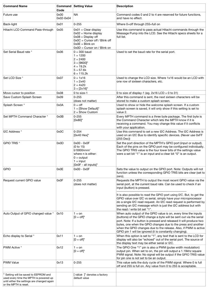
The ICSP: In circuit serial programmer port is used to program the on board PIC microprocessor. The MPTH is set-up so that if the VPP pin is connected to ground on power-up if resets to factory defaults.
1. Turn off the Message Pump.
2. Short the VPP pin to ground. (Use a wire to connect this pin to GND)
3. Power ON the Message Pump.
4. You will see a message “Resetting”, after a moment you will see the default splash and info screens appear.
5. Power OFF the Message Pump.
6. Undo the connection from VPP to ground.
7. The Message Pump is now reset.
NOTE: This does not replace the custom Splash Message. To replace the custom message you simply re-save a new splash message over it.

Tools Required:
Soldering Iron:
Solder for electronics: If you get the lead free type make sure that your soldering iron works with it. (Lead free solder normally requires more heat then the leaded type.)

Flush cutters: Used to cut off the leads after they are soldered.
Wear Safety Glasses: These cutters will send a lead flying across the room!
Step 1:

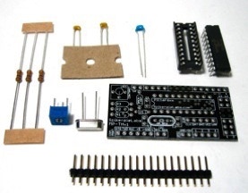
Clear a space to work and gather up your parts.

Step 2:
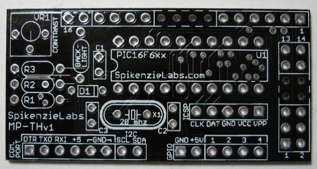
Position the PCB (Printed circuit board) so that the white silkscreening is on the top side and readable.
Warm-up your soldering iron.
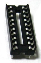
Insert the 20 pin socket into the spot marked U1. The rounded edge of the socket should point to the left.
Solder it in place.
Step 3:
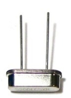
Insert the crystal into the spot marked X1.
Solder it in place, you may need to hold in on with masking tape when you flip the board.
Snip the leads after it is soldered in place.
Step 4:
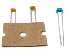
Insert the capacitors in place.
The blue capacitor is C1
The two yellow capacitors are C2 and C3.
You can bend the leads a bit to hold them in place. Solder the capacitors and then trim the leads.
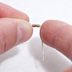
Step 5:
Using only your fingers bend the leads at a 90 degree angle to the body of the resistors.
Next, place the resistors into the PCB in the places marked R1, R2 and R3. Orientation does not matter.
After the resistors are soldered in place, inspect the solder joints then trim the leads to be nearly flush with the PCB.
Note:
1. If you are using an LCD with backlighting that requires a current limited resistor, place it (not included) in the spot marked “BACK-LIGHT”. (If your backlighting does not require a resistor, then jumper this resistor with a wire.)
2. If your application has an I2C bus that has pull up resistors already you can omit R2 and R3.
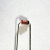
Step 6:
Bend the diode using the same technique as the resistors and then put it in the spot marked D1.
Important: The band on the diode goes on the same side as the band printed onto the PCB.
Solder and trim.
Step 7:
Place the trim pot in the spot marked VR1 “Contrast”.
Solder and trim it’s leads.
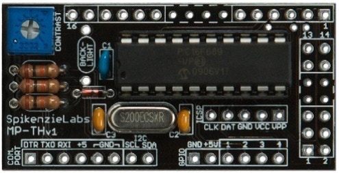
Step 8: Now you should have something that looks like this .
How or if you install the pin header is up to you, and will depend on how you are going to use the MPTH and with which type of display.
The center four spots on both the 1x16 or the 2x7 LCD connectors do not have solder pads and no pins are required here. The MPTH does not use these pins to connect to the displays, the holes are there so you don’t have to cut your pins if they are already soldered to onto your display.
Important: The LCD goes on the back-side of the MPTH

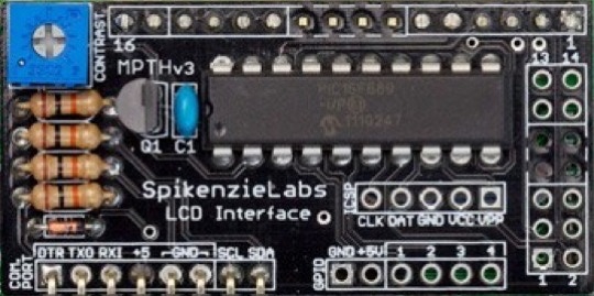
Our newest version of the SpikenzieLabs LCD Interface (MPTH v3) has all of the great features of the previous MPTH LCD interfaces but now also has a variable digital back-light control.
Changes to the build instructions:
The new version has fewer parts; no crystal etc... Building version 3 is an easy build and almost the same as the previous one. Note: All the resistors are the same value (10k ohm), for the transistor, match it’s position to the white silkscreen.
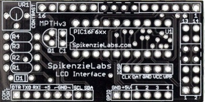
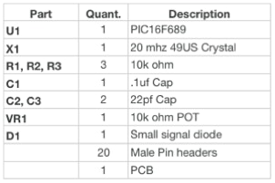
SpikenzieLabs LCD Interface (MPTH v3) Part list
U1 PIC16F689
C1 0.1uf Cap
R1-R4 10k ohm
D1 Small signal diode
VR1 10k ohm trim pot
Q1 PN2222 transistor
New Back-Light function:
The new backlight function is command number 1. Download the most recent command list PDF here.

Copyright SpikenzieLabs 2019