Gets a single unique button press value from a matrix of 8x8 (64) push buttons.
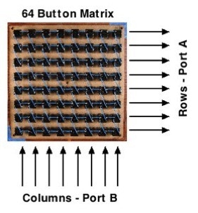
Decoding a button press is done with the help of a MCP23S17 port expander from Microchip . This chip has 16 general purpose I/O pins (GPIOs). Eight I/Os are used for the columns and other eight for the rows, forming a 64 button matrix. The columns (port B of the MCP23S17) are set-up as outputs and the rows (port A) inputs.
One of the great features of this project is that there are no diodes! Unlike many button matrices, it’s just the buttons and the MCP23S17.
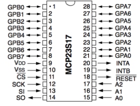
Pin out of the MCP23S17 port expander used to interface with the button panel.
The pins on port A are pulled high using the internal weak pull-up resistors. This means that if a button is not being pressed, and port A were to be read, all the eight pins would be high. Rather then continually reading port A to see if there is a button press, we configuring the MCP23S17 to cause an interrupt any time pins on port A changes from the pulled-up high value.
In order to cause a pin on port A to go low (and cause an interrupt) two conditions must be meet, 1. A button must be pressed and 2. The output of the Port B column must be cleared to low.
Here are two ways to initiate button press sensing;
Method A: "Wait for an interrupt and then decode Method": If your Micro has the ability to sense and handle (IOCs) pin interrupts on changes then all you have to do is clear (set to low) all of the pins of Port B and wait for a change on port A to cause an interrupt. Once an interrupt is sensed, your Micro would then need to cycle through the port B pins one at a time to see which column caused the interrupt. The result is the row and column value that can easily be decoded.
Method B: "Once a loop, cycle through the columns": This is the method that is used in the Arduino Sketch " Button64v4.pde ". Here once every program loop, a call is made to a function that changes each of the columns (port B) pins to a logic low, one at a time. If an interrupt is sensed (the interrupt pin on the MCP23S17 goes high) the column is already know since the sketch controls the columns, port A is read to get the row. Then with just a bit of code, a unique button value is achieved.
Animation demonstrating the scanning of the buttons.
If we think of each of the 64 buttons as a bit and if your hands were big enough (or you had help from a few friends) you could press a total of 18446744073709551615 different combinations of the 64 buttons!
The intention of this project is not to decode that many choices, but rather just 64. The way the Arduino sketch does this is by checking one column at a time. It starts with the left-most column and works it’s way right. Then as soon as it sense a button press it stops. This is a form of priority encoding because the buttons on the left side (if more then one column are being pressed) will be decoded and the buttons pressed more to the right would be ignored.
If on the other hand more then one button is pressed in two or more rows, the sketch considers that an error and ignores the input, and continues through the program loop.
The MCP23S17 port expander uses the Serial Peripheral Interface (SPI) a form of synchronous serial data standard. It is synchronous because there is a clock line that controls the data transmission. SPI uses four wires to communicate in two directions.
If we use the this project as an example, the Arduino running the Button64 sketch is called the SPI Master and the button matrix is called the SPI Slave. The master device always controls the communications and the the clock line.
The four SPI signals:
SCLK = Serial clock
MOSI = Master Output Slave Input
MISO = Master Input Slave Output
CS = Slave Select
Extra signal:
INT A = Interrupt on Port A (This is only for the button matrix, and is not a normal SPI signal)
The type of buttons used to make this button matrix are push style SPST-NO (Single position single throw). This means that there is only one circuit going through the button, and when the button is not being pressed it is normally open (the circuit does not conduct).
If your buttons have two or four pins coming out the bottom it does not matter, just make sure that as you solder your rows and columns that they are common all the way up or across.
Video of the long process of soldering all 64 buttons. It took 1h 35min.
Once you have all the buttons connected in rows and columns, make 16 extra wires and solder one end of each to every row and column. It does not matter where along each row and column that you solder them, so just pick the spot that you like the best; top, bottom, middle etc.
You should end up with 16 wire ends. If you haven’t already, pick which orientation is going to be the columns and rows.
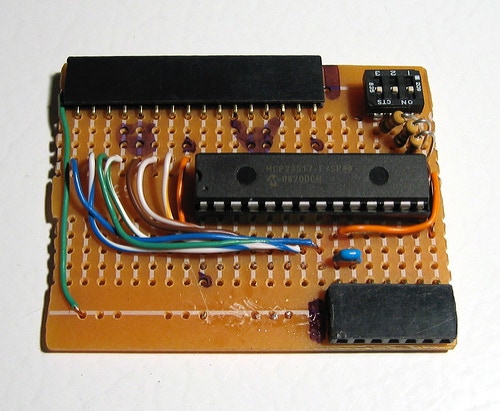
Quick and dirty - Hardware interface for the button panel.
Using the free ends of the wires in the last step; connect the wires from the columns to port B of the MCP23S17. Starting with column “1” connected to GPB0 (Pin 1), continue with column “2” to GPB1 (pin 2) and so on until all the columns are wired to the MCP23S17.
The rows are wired in a similar manner starting with row “1” being wired to GPA0 (pin 21) all the way to row “8” going to GPA7 (pin 28).
Connect pin 9 to +5 volts and pin 10 to ground. You should also connect pin 15, 16 and 17 (Address A0, A1 and A2) to ground. The Button64 sketch does not use these addresses.
Pin 18 (reset) should be connected to +5v though a 10K ohm resistor.
Connecting the hardware interface to an Arduino;
SIGNAL MCP23S17 ARDUINO
Slave Select CS (pin 11) Digital 5
Serial Clock SCK (pin 12) Digital 3
MOSI SI (pin 13) Digital 2
MISO SO (pin 14) Digital 4
Interrupt INTA(pin 20) Digital 6
I. Make a button panel following the wiring instructions above.
II. Wire-up the MCP23S17.
III. Hook it all to your Arduino.
IV. Download the Arduino sketch Button64v4.pde , compile it and then upload it to your Arduino.
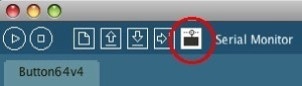
V. Click on the open Serial Monitor icon.
Make sure that it is set to 9600 baud (Look near the lower part of the Arduino window)

VI. If everything is good, after a moment, you should see the word “Ready” printed in the bottom part of the Arduino IDE (white text on black). Then, if you press some buttons you will see the button numbers, followed by “OK” after you release the button.
What’s next:
After you get your button board working with the Serial Monitor, you can comment out “//” the lines of code that send the serial messages for testing.
The Button64 sketch will return the last pressed button value in the variable called “buttonPress”. With this you can build your own sketch / project and use the button value to make music, light LEDS, turn on motors, make a sequencer ...
Do you think that 64 buttons has too many buttons, or would be too long to wire-up? You can always make a smaller button panel! If you use the same construction techniques for the rows and columns, it will work with-out changing the sketch! (Note: if your rows are less then 8 buttons wide the button value returned will still jump by 8 for each row.) Unused port pins on the MCP23S17 may be left floating (not connected).

We wanted our to have a finished look. After looking around for lots of buttons we decided to use a bag of surplus button we had on hand. Here are the steps we took to make nice looking button tops.

I had a lot of this style of surplus buttons. Note the “x” shape on top to receive the button top. I didn’t have the tops so I decided to try making some on our laser cutter.

First I etched numbers into the button tops. To colour the numbers I applied acrylic paint. Since the numbers where etched into the plastic being neat did not matter too much.

After the paint was dry, i cleaned and sanded the button tops. This removed the excess paint to make the numbers nice an clear.

The white top of the button tops is flat and would not stick to the “x” shape on the actual buttons. To make them stay on I cut out the “x” shape in the same pattern as the etched numbers on a 1/4” thick piece of acrylic. The sheet with the “x” shape cut parts was then glued onto the white etched sheet.

The circular shape of the buttons was then cut to free all the buttons from the sheet.

Button panel is ready to receive the now cut button tops.

Button tops installed on all the buttons.

Here is the drawing file used to cut out the plastic parts.

Copyright SpikenzieLabs 2019
