

Here is our own video of us having fun our wrap it up box at the office.
The Wrap it Up Box is from a sketch on the Dave Chapelle show. It is a box that plays “award show wrap it up” music and flashes the message “WRAP IT UP”, it is used to let guests know that it is time to “Wrap it Up” and get off the stage.
The Chapelle show takes the “Wrap It Up Box” to hilarious ends by using it in every day situations, like the sketch where a guy is at the restaurant with his girlfriend and, she won’t stop talking.
No need to paint that box of tissue paper silver, here you will find the instructions, parts list, Arduino sketch and cut list to make your very own, solid as a rock, Wrap it Up Box. Here is the parts list.
Wood glue
Hot glue [Optional]
5 Minute (2 part) Epoxy
Double Sided tape or foam
Solder
Silicone sealant - clear
Primer
Silver spray paint
Black acrylic paint
Biscuits #0 [Optional]
Baltic birch plywood (~24”x11” and 11.5mm ~15/32” thick) - Main box
Solid or plywood scraps (3/4"x3/4"x12") - Corner supports
Hardboard 1/8" thick (8”x11”) - Back panel
Black 1/8" thick (~5”x5”) acrylic sheet - for speaker grill
Translucent 1/8" thick (~ 7”x7”) acrylic sheet - for flashing message area
Table Saw
Router with 3/8” Rabbeting bit [Optional]
Laser Cutter [Optional]
Soldering Iron
Hot Glue Gun [Optional]
Wire cutters
Computer with Arduino IDE
Audio cable with 3.5mm male jack
USB Cable - for Arduino
Paint Brush
Paint Scraper
Sander / sand paper / sanding block
Biscuit Jointer [Optional]
Drill with hole saws (1 1/8” + other sizes if needed)
Clamps
Stand off + Screws x2 OR Screws + spaces x2 - To mount Arduino
Wood screws (#6 3/4”) for back panel x4
Screws (#6 1/4”) for speaker x4

After you have collected the materials, start by cutting the sheet of plywood as per the diagram below. The best tool for the job is probably a table saw.
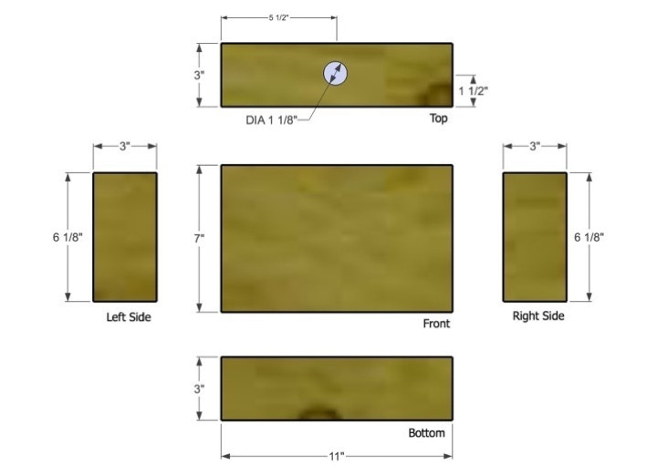
If you have access to a laser cutter, you can simply send the front panel pdf file to the laser to cut out the speaker hole and the flashing message area.
If not, print out the front panel on a laser printer at a 1 to 1 sizing and trace it onto the front panel wood, then cut the two holes with a hole saw and or jig saw.
After the two holes are cut, sand the inside edge smooth (especially important if you are using a router in the next step).
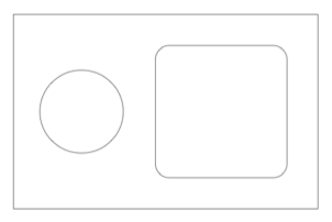
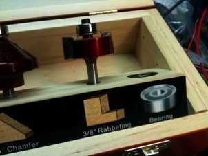
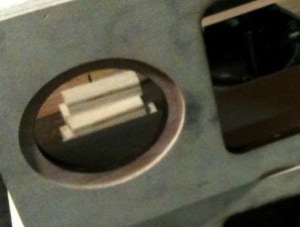
There are two other optional cutting steps to the front panel. On our version of the box we used a router to cut a 3/8” rabbet around the outside of the speaker grill hole and from the inside of the message area. These rabbets allow the speaker grill and message panel to fit snugly into the front panel of the box and were cut 1/8” deep to match the thickness of the plastics.
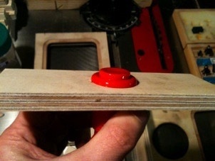
Using a 1 1/8” hole saw cut the hole for the big button in the piece that will be the box top.
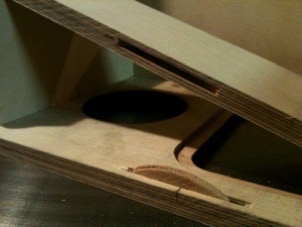
If you have access to a biscuit jointer, using it will give you an exceptionally strong box (and easier to build). Carefully mark the spots were you want to make your joints. Check them twice before cutting! Set you cutter to the smallest size biscuit some times #0 or #00. Make your cuts.
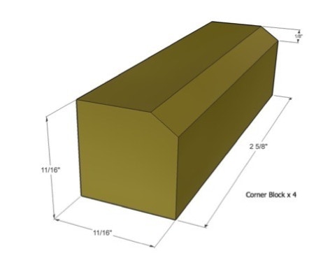
Make four corner supports to match the following illustration. The bevel edge can be made by simply sanding. These are non critical dimensions but the length should be the same on all four, since they are used to hold the back in place.

On our version of the Wrap it Up Box the speaker grill was laser etched and cut. Overkill, maybe. If you want to laser your own here is the Speaker Grill pdf file . If not, there are a bunch of great looking speaker grills that you can get at audio shops or you could just use some black cloth.


The front message panel is a back etched sheet of translucent white acrylic. We back etched it (with the text flipped) so that the etching would be protected from people’s fingers and so that the message is a little more hidden unless the box is flashing. Cut and etch your own with this file, Flash Window pdf.
If you are making your box by hand and would like get your hands on a laser cut panel with this or another message check here .


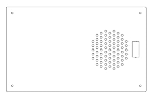
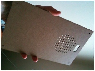
The back panel is simply a rectangle of 1/8” hardboard. We used this Back Panel.pdf to cut it out on the laser. Any backing should do, here I added holes behind the speaker because it seemed like it would help let the sound out. The button hole was made for the button we had on hand, so if you use this file, you will probably have to edit it a bit.

Here are the steps to build the box. Start by test fitting all the parts and make adjustments as needed.
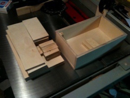
Make sure you have enough glue (and biscuits if you are using them). Starting with the sides, apply glue to two mating edges and press together, continue until all four sides are glued.
Don’t stop here!
Apply and spread glue around the edge the will match up with the front. Fit the front panel onto the sides and adjust the position. Use your clamps to hold the parts tightly together. If your clamps don’t have rubber ends it is good idea to use scraps of wood to protect the box’s wood surface from damage.
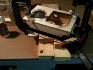
Sand the box all over. We used a router with a 1/4 round bit to give our box a nice rounded look.
Recheck the position of the parts, they will often move as the clamps are tightened.
Let glue cure.
Once the glue is solid, remove the clamps. And glue in the four corner supports. The edge with the bevel goes into the corner.
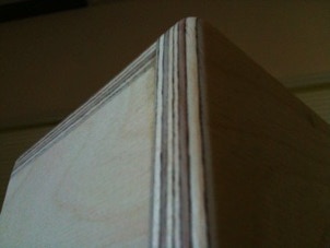
Wood tends to absorb a lot of paint when it is not sealed, so we painted ours with white primer first. Primer also makes the paint look more even colored.
But don’t do what we did; we painted the primer in direct sunlight and the primer dried as it was applied and made the surface lumpy. So, we had to do a lot of sanding afterwords.
Once the primer is dry and you have re-sanded (if needed!), give the box few light coats for silver spray paint.
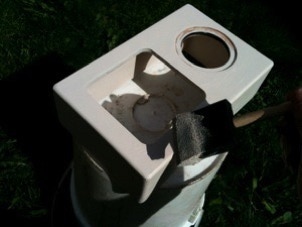
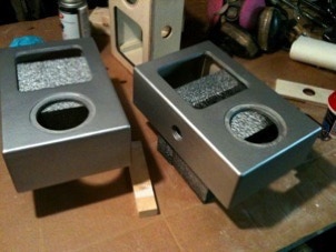
While the silver paint is drying you can prepare the front message panel. If you are using a laser etched acrylic panel then only use acrylic paint for the letters. (Other types of paint seem to make small cracks in the plastic.) Paint the inside of the etched area with black paint, let it dry. If you got paint outside of a letters, wait until after the paint is dry and use a razor blade type paint scraper while holding it at a low angle.
Speaker and front message panel installation:
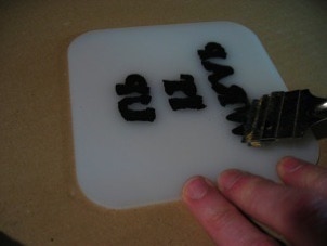
Using clear silicone clacking apply a thin bead around the rabbet that was cut in the front panel. Don’t apply too much so that it squirts out, but do make a complete bead so that the panels don’t rattle. Press the panel into the silicone being sure that it is upside right! Repeat for the speaker grill, but from the outside of the box.
Center the speaker over the speaker hole and using very short screws, fasten it to the front of the box, from the inside. You may want to hold the screw against the side of the box to make sure it won’t go all the way through.
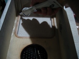
Using your Arduino as a guide, mark two spots for the mounting screws. Choose a spot that won’t cast a shadow on the front message panel and make sure that the stack of Arduino, ShiftBrite shield and VoiceShield won’t get in the way of the speaker.
We drilled small pilot holes for our screws and used masking tape as a depth guide. A regular drill wouldn’t fit so a bendable shaft was used instead.
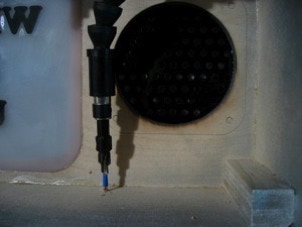
Stand-offs can be screwed directly into the wood (with pilot holes) or you can use small plastic spacers and simply screw the Arduino directly onto the wood.
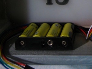
The batteries fit nicely under the message panel. Use double sided tape / foam to attach the battery holder.
Attach the black wire from the battery pack to the GND screw terminal of the ShiftBright Shield.
Remove the switch and lock nut from the big button. Insert it into the hole and tighten in place with the lock nut. Reattach the switch, to the plunger part of the button. Connect the two button wires to COM. and the NO. terminals of the button’s switch.
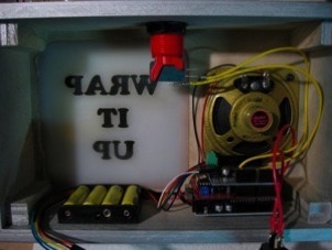
Using epoxy, glue the ShiftBrite assembly to the back panel and let the epoxy set.
Using a triangle formation for the ShiftBrites works well to light up the message area. With the triangle standing with it’s point up. Attach the six wire cable from the first ShiftBrite to the connector on the ShiftBright Shield. Double check the polarity of the wire to match the correct pins!
Press the power switch into the back panel and connect the two wires to it, one from the battery pack and the other to the VIN screw terminal of the ShiftBright Shield.
Also, connect the two wires from the speaker to the Speaker connector on the VoiceShield.
Insert batteries and test the box. If needed, adjust the volume trimmer pot on the VoiceShield.
Screw the back panel in place.
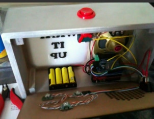

The Wrap it Up Box’s electronics is actually a mix of parts from a bunch of sources. There is button from SparkFun, ShiftBrites from Macetech, our very own VoiceShield and a handful of bits and pieces from the local surplus shop.
Below is a “schematic” of the Wrap it Up boxes electronics, even though there is no actual Wrap it Up Box PCB. All the parts are simply connected together with wire we found on the work bench.
Power from the battery pack is diverted though an on / off switch. When the switch is in the on position power flows into the ShiftBrite Shield’s screw terminal power connector. From there the power flows from the ShiftBrite Shield down to the Arduino’s VIN pin. The Arduino’s VIN pin is connected to an on board +5 volt regulator. This +5 volts powers the rest of the Arduino and the VoiceShield.
The Arduino sketch runs in a loop, checking if the Big Button has been pressed. If the Wrap it Up Box was silent before the button press, it tells the VoiceShield to start playing the song and at the same time sends alternating full red and off signals to the ShiftBrites via the ShiftBrite Shield. If the song plays to the end of the recording, the Arduino tells the VoiceShield to start it over again at the beginning.
If the box was “playing” before the button was pressed it tells the VoiceShield to stop and the ShiftBrites to turn off.
An easy hack at this point would be a selector switch, to choose different sounds to play or different colors to flash!
Most of the electronics build is simply stripping around 1/8” - 1/4” of the ends of a bunch of wires and either soldering them onto terminals or crimping them into removable connectors.
You will need two lengths of wire for the Big Button. Make them long enough so that they reach the ShiftBrite Shield and that there is enough slack on them to move parts around for changes. These are the yellow wires in the photo below.
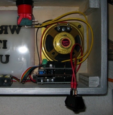


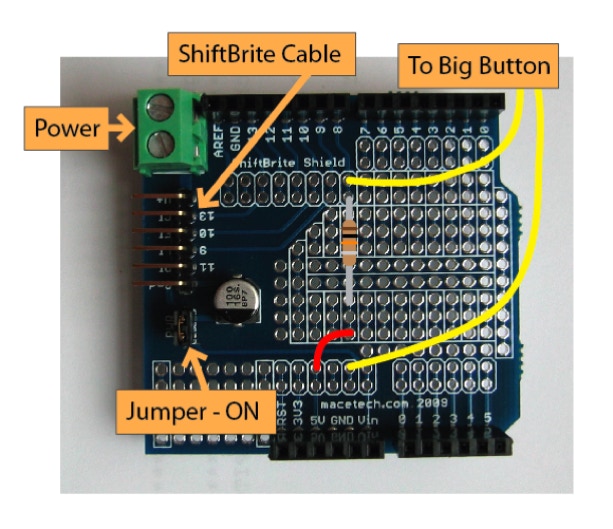
Connect one of these wires from the button to a spot on the ShiftBrite Shield that is marked GND. Connect the other wire to the pin marked “8”. Also connect a 10k ohm resistor from the pin “8” to +5 volts. (This causes pin 8 to be pulled high, meaning if the button isn’t pressed then reading pin “8” will return high (+5volts). You may also need a small length of wire, be careful not to short the resistor to any other pins. When the button is pressed pin “8” is connected directly to ground and reads low (0 volts).
Connect two wires to the power switch. One of the wires goes to the + side of the battery pack and the other goes to the VIN screw terminal on the ShiftBrite Shield.
Connect another two wires to the connector tabs on the speaker. The other ends of these wires connect to the spot marked “Speaker” on the VoiceShield. If your speaker’s tabs are marked with + and -, then connect them with the correct orientation on the VoiceShield.
For the three ShiftBrites that are going to be glued onto the back panel, connect three of them together by soldering some short lengths of wire from the Outputs of one ShiftBrite onto the Inputs of the next ShiftBrite. Once that is done, solder on a longer set of six wires (or use one of the nice pre-made six wire cables) from the Input side (very important !) of the ShiftBrite that does not have any wires connected to the input side. The other end of this six wire cable goes on to the ShiftBrite Shield.
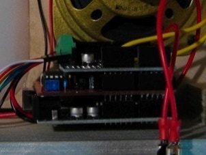
After you have done all the soldering and mounted the Arduino to the bottom of the box, you can stack on the other two shields. It doesn’t matter with shield goes on first, we played with the order a bit just to route the wires more easily.

There are two main steps to set up the Arduino sketch and music.
The first step is to load the VoiceShield with your choice of cheesy music for the Wrap it Up Box to play. For our version of the box, we used a GarageBand jingles sample called “Starlight Lounge”. Using the VS_Loader sketch we loaded this sample starting at sound slot 1. See the VoiceShield web page for a full description of how to load and program the VoiceShield along with all the Arduino demo sketches and sample sounds.
After the VoiceShield is loaded with audio, the next step is to upload the Wrap It Up Box Sketch into the Arduino.
Download the Wrap It Up Box Sketch here: WrapItUpBox2.pde.zip
Once the Arduino Wrap It Up Box sketch is uploaded, and you have the wires and shields connected, you should be able to test the box.


Copyright SpikenzieLabs 2019
