The idea here is to make a board that I can interchange gears on a whim, and see the different speeds that gears turn in ‘real life’. For inspiration, I flipped through one of my most all time favourite books, 507 mechanical movements. Now available for free online, http://507movements.com Love it!
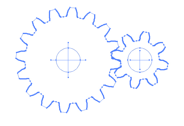
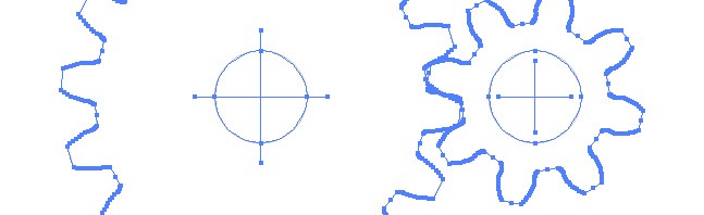
With the gears created, I exported them as PDF, and then into Adobe Illustrator. There is a command in illustrator to ‘Simplify’. This makes laser cutting much simpler. Strongly recommend using that command on CAD / other output files before cutting. Here is an example of one of the gears in illustrator.:
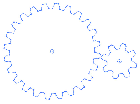
Note the fewer line segments that appear on a gear after using the simplify command. (Blue dots).
Above is the main drive gear, with the spindle cut out. My measuring was very exact. Took about 5 pounds of force to get the acrylic gear squished onto the spindle. I think some of the residue from the tape testing is lending a hand keeping it solid. The blue colored board is actually clear acrylic with blue protective film still in place.
I based the spacing on a .5″ spacing, so any of the gears that I’ve generated can mesh perfectly with any other. The holes are laser cut at .08″. This is the perfect size to send a 4-40 tap through.
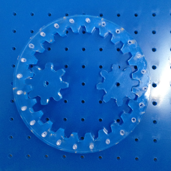
Note how you can see right through the center hub of the two gears above. This was the pint that I started to feel really great.
Tapping acrylic is something we first tried years ago on our Povard POV electronics kit. Since then, we’ve been tapping acrylic at a feverish pace, and have burnt through a few drills.
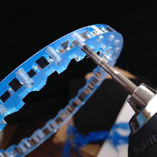
Here is how we tap. The tap going through a 1/4″ ring gear. I have centered some holes at 15 degree increments. Zipping the drill in, and reversing it out leaves a very solid threading in the acrylic. Doing it at high speed versus low speed makes no difference.
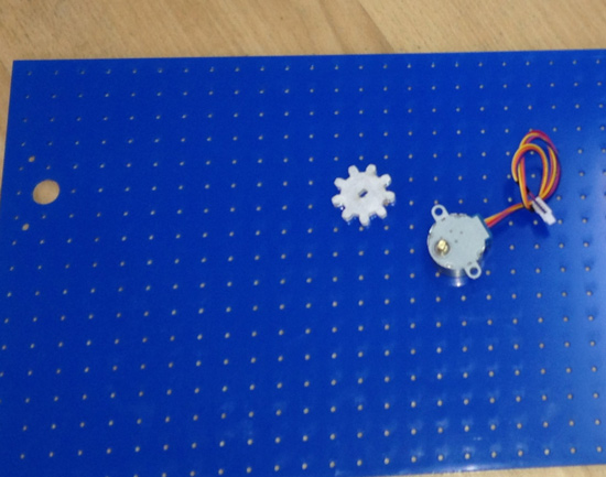
Creating a stepper motor mount was pretty simple. I need the center of the stepper spindle to be coming through one of the holes in my board. I lined up the mount holes on the stepper, and cut them through the .5″ spacing hole board.
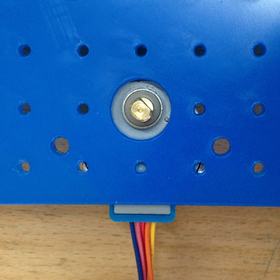
Notice how you don’t see the mounting brackets of the stepper? Measured out perfectly they are directly below the holes cut in the acrylic.
Fitting it all together, I slid the main drive gear back in place, and then loaded in the rest of the gears. Tapping only the holes that I need to use.
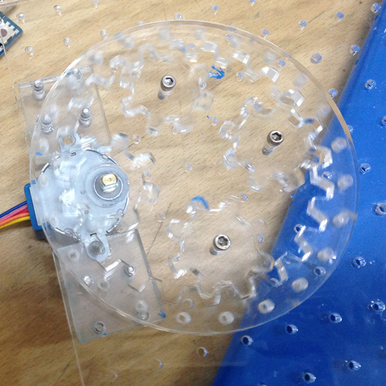
Last minute change for the mount.. I realized that I didn’t have the clearance under above the motor mounts to send a nut & bolt through, so I made a pressure fit pinch plate. This way I don’t need to counter-sink the mount holes. Peeling away the blue protective sheet underneath.
A few other gears created, a push-bar, and here is what I ended up with.
Stepper Motor & Gear Testing a video by SpikenzieLabs on Flickr.